Marine vessel

A technology for ships and sterns, which is applied on opposite sides for the field of ships, can solve problems such as hindering propulsion efficiency, and achieve the effect of preventing damage

Inactive Publication Date: 2019-07-02
MEYER TURKU
View PDF7 Cites 2 Cited by
  • Summary
  • Abstract
  • Description
  • Claims
  • Application Information

AI Technical Summary

Problems solved by technology

In some operating modes of known ships, this can solve the vibration problem, but the known solutions strongly hinder propulsion efficiency combined with sufficient steering capability

Method used


Image

  • Marine vessel
  • Marine vessel
  • Marine vessel

Examples


Embodiment Construction

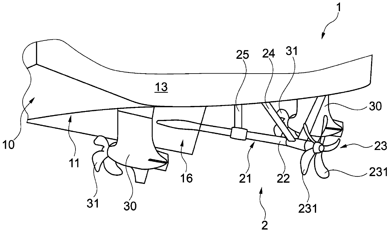
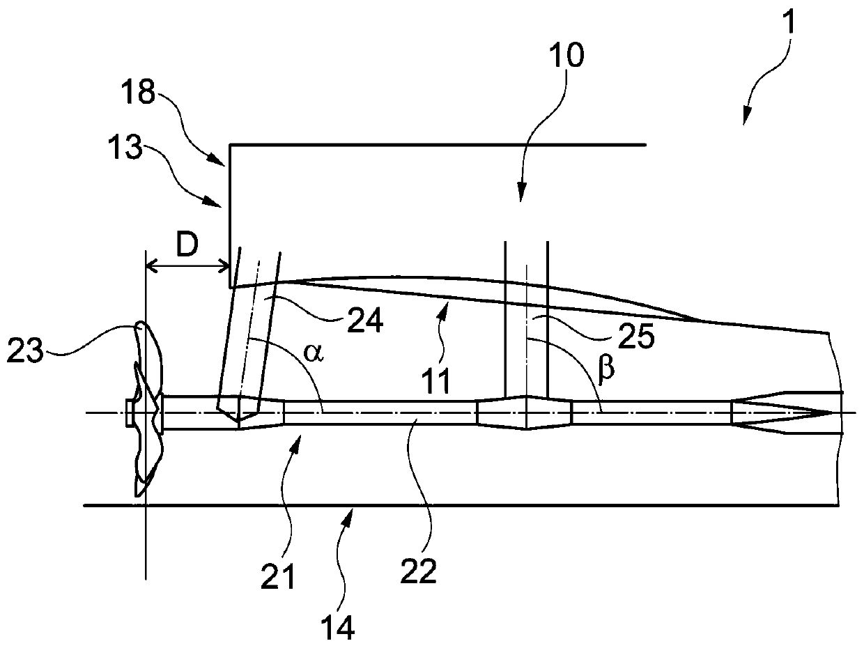
[0028] figure 1 The vessel 1 is shown from the stern side. The vessel is provided with a hull 10 with a bottom 11 , a bow (not shown), a stern 13 and a propulsion device 2 arranged at the stern of the vessel. The vessel has a centerline skeg 16, a baseline 14 ( figure 2 and image 3 ) and centerline 15 ( image 3 ). The bottom 11 approaches and reaches the base line 14 .

[0029] In this embodiment, the vessel is provided with a propulsion arrangement 2 comprising three propulsion units, a fixed centerline shaft propulsion unit 21 with an axis 22 and a propeller 23 and two rotatable propulsion units with corresponding propellers 31 Unit 30. A fixed centerline shaft propulsion unit 21 is arranged to apply thrust in both forward and rearward directions. Rotatable propulsion units 30 are arranged one on each side of the centerline shaft propulsion unit 21 and are arranged for steering of the vessel. The rotatable propulsion units 30 are arranged symmetrically on opposite...


PUM


Abstract

The present invention relates to a marine vessel (1) with a hull (10) with a bottom (11), a bow, a stern (13), and a propulsion arrangement (2) including at least three propulsion units arranged at the stern of the marine vessel. The marine vessel (1) has a base line and a centerline. The at least three propulsion units include a centerline shaft propulsion unit (21) with a shaft line (22) and a propeller (23) and two turnable propulsion units (30) with respective propellers (31) and arranged at opposite sides of the centerline shaft propulsion unit. For improving thrust efficiency, while maintaining optimal steering capability, the propeller (23) of the centerline shaft propulsion unit (21) is arranged at a given distance aft of the stern (13) of the marine vessel (1).

Description

technical field [0001] The invention relates to a vessel having a hull with a bottom, a bow and a stern, the vessel being provided with propulsion means comprising at least three propulsion units arranged at said stern of said vessel, and said The vessel has a baseline and a centerline, wherein said at least three propulsion units comprise a fixed centerline shaft propulsion unit having a shaft and a propeller and having respective propellers and arranged at opposite sides of said fixed centerline shaft propulsion unit for said Two rotatable propulsion units for ship steering. The invention also relates to a propulsion device and a method of providing a propulsion device to a ship. Background technique [0002] It is known from the prior art that ships are provided with at least three propulsion units in the stern. Examples of such approaches can be found eg in WO 03 / 066428 A1, WO 03 / 099651 A1, WO 2006 / 048460 A1 and WO 2009 / 007497 A2. These known solutions are mainly conc...

Claims


Application Information

Patent Timeline
Patent Type & Authority Applications(China)
IPC IPC(8): B63H5/08
CPCB63H5/08B63B1/08B63H1/28B63H2005/1254B63H2025/425B63B3/42Y02T70/10B63B73/20B63H1/14B63B39/12B63B73/00B63B1/04
Inventor R·哈马莱宁
Owner MEYER TURKU
Why Eureka
Try Eureka