Deicing robot
A technology of robots and airframes, which is applied in the direction of rotorcraft, manipulators, aircrafts, etc., can solve the problems of high risk factor, inconvenient transportation, high labor intensity, etc.
- Summary
- Abstract
- Description
- Claims
- Application Information
AI Technical Summary
Problems solved by technology
Method used
Image

Examples
specific Embodiment approach 1
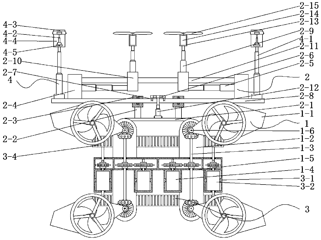
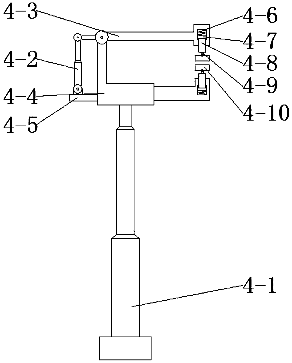
[0036] like figure 1 As shown, a deicing robot includes: unmanned body 1, ice removal device 2, running device 3 and fixing device 4; connected, a plurality of fixing devices 4 are arranged symmetrically on the ice clearing device 2;
[0037] The ice clearing device 2 comprises: a fixed plate 2-1, a fixed rod 2-2, a first fixed block 2-3, a second fixed block 2-4, a first hydraulic cylinder 2-5, a drive shaft 2-6, a drive connection Rod 2-7, connecting rod 2-8, second hydraulic cylinder 2-9, slide block 2-10, slide bar 2-11, third hydraulic cylinder 2-12, motor housing 2-13, drive motor 2-14 and deicing blade 2-15; the fixed plate 2-1 is fixedly connected with the drone body 1, and the fixed plate 2-1 is symmetrically provided with a plurality of fixed rods 2-2, and one end of the fixed rod 2-2 is connected with the fixed plate 2-1 Fixed connection The other end is fixedly connected with a first fixed block 2-3, the inner side of the first fixed block 2-3 is provided with a ...
specific Embodiment approach 2
[0041] combine figure 1, this embodiment is based on the specific implementation mode 1, the difference is that the drone body 1 includes: a drone propeller 1-1, a connecting plate 1-2, a first drive rod 1-3, a first drive Motor 1-4, first housing 1-5 and steering drive rod 1-6; the lower end surface of the housing is symmetrically provided with a plurality of connection plates 1-2, and the lower end surface of the connection plate 1-2 is connected with the fixed plate 2-1 is fixedly connected, the rotation on the connecting plate 1-2 is connected with a plurality of steering drive rods 1-6, and the side of the steering drive rod 1-6 is fixedly connected with a UAV propeller 1-1, and the first housing 1- A plurality of motor installation cavities are symmetrically arranged in the 5, and a first drive motor 1-4 is arranged in the motor installation cavity, and the first drive motor 1-4 is rotationally connected with the interlayer of the motor installation cavity through a bear...
specific Embodiment approach 3
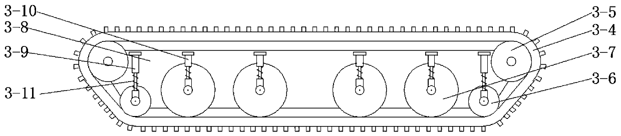
[0044] to combine Figure 1 to Figure 2 , this embodiment is based on the specific implementation mode 1, the difference is that: the traveling device 3 includes: a second housing 3-1, a second driving motor 3-2, a second driving rod 3-3, and a chain rail 3 -4, driving wheel 3-5, first driven wheel 3-6, second driven wheel 3-7, mounting plate 3-8, first telescopic link 3-9, second telescopic link 3-10 and spring 3- 11. Two second shells 3-1 are symmetrically welded on both sides of the first shell 1-5, and each second shell 3-1 is provided with a motor installation cavity, and a second motor installation cavity is provided in the motor installation cavity. The drive motor 3-2, the main shaft of the second drive motor 3-2 runs through the outer wall of the motor installation cavity, the second drive motor 3-2 is rotationally connected with the second housing 3-1 through the bearing, and the second drive motor 3-2 passes through The gear mechanism is connected with the second d...
PUM
 Abstract
Description
Claims
Application Information