A deicing robot
A technology of robots and airframes, applied in aircraft, rotorcraft, manipulators, etc., can solve problems such as inconvenient transportation, high labor intensity, and high risk factor of operation, and achieve the effects of avoiding falling off, reducing labor intensity, and improving safety factor
- Summary
- Abstract
- Description
- Claims
- Application Information
AI Technical Summary
Problems solved by technology
Method used
Image
Examples
specific Embodiment approach 1
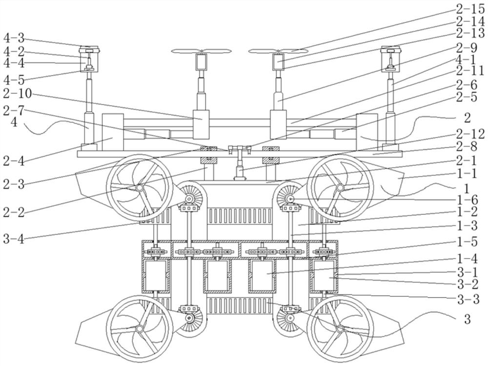
[0036] Such as figure 1 As shown, a deicing robot includes: unmanned body 1, ice removal device 2, running device 3 and fixing device 4; connected, a plurality of fixing devices 4 are arranged symmetrically on the ice clearing device 2;
[0037] The ice clearing device 2 comprises: a fixed plate 2-1, a fixed rod 2-2, a first fixed block 2-3, a second fixed block 2-4, a first hydraulic cylinder 2-5, a drive shaft 2-6, a drive connection Rod 2-7, connecting rod 2-8, second hydraulic cylinder 2-9, slide block 2-10, slide bar 2-11, third hydraulic cylinder 2-12, motor housing 2-13, drive motor 2-14 and deicing blade 2-15; the fixed plate 2-1 is fixedly connected with the drone body 1, and the fixed plate 2-1 is symmetrically provided with a plurality of fixed rods 2-2, and one end of the fixed rod 2-2 is connected with the fixed plate 2-1 Fixed connection The other end is fixedly connected with a first fixed block 2-3, the inner side of the first fixed block 2-3 is provided with...
specific Embodiment approach 2
[0041] to combine figure 1, this embodiment is based on the specific implementation mode 1, the difference is that the drone body 1 includes: a drone propeller 1-1, a connecting plate 1-2, a first drive rod 1-3, a first drive Motor 1-4, first housing 1-5 and steering drive rod 1-6; the lower end face of the first housing 1-5 is symmetrically provided with a plurality of connecting plates 1-2, and the connecting plates 1-2 The lower end surface is fixedly connected with the fixed plate 2-1, and the rotation on the connecting plate 1-2 is connected with a plurality of steering drive rods 1-6, and the side of the steering drive rod 1-6 is fixedly connected with the UAV propeller 1-1, the first A housing 1-5 is symmetrically provided with a plurality of motor installation chambers, and a first drive motor 1-4 is arranged in the motor installation chamber, and the first drive motor 1-4 is rotationally connected with the interlayer of the motor installation chamber through a bearing...
specific Embodiment approach 3
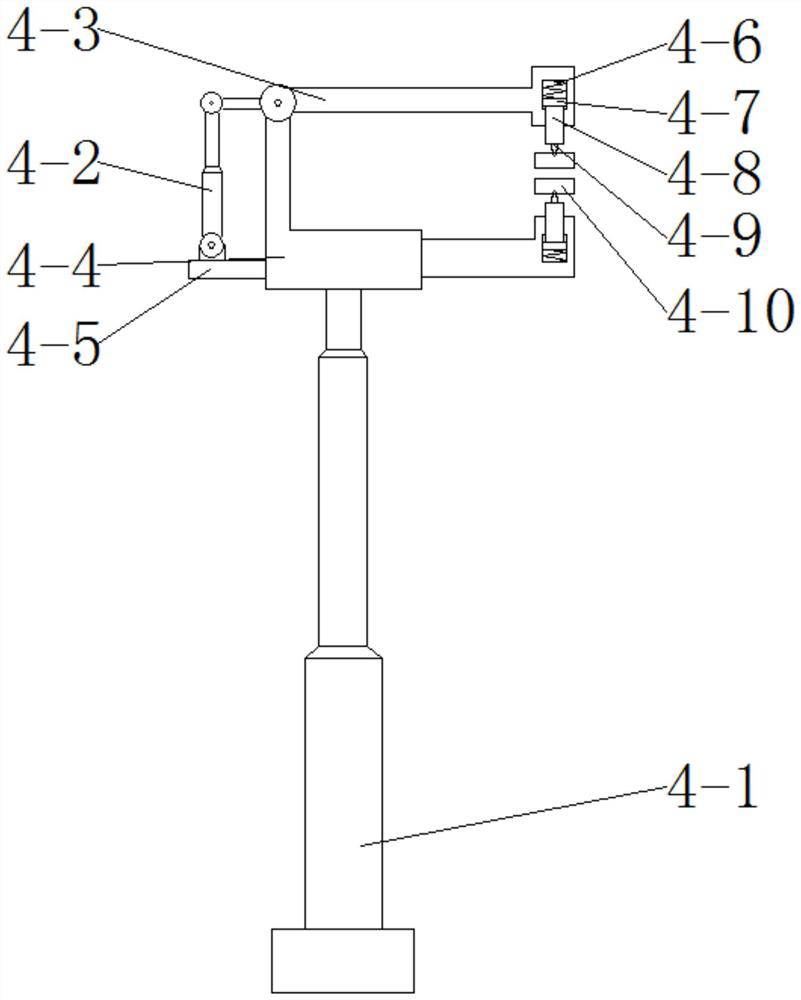
[0044] combine Figure 1 to Figure 2 , this embodiment is based on the specific implementation mode 1, the difference is that: the traveling device 3 includes: a second housing 3-1, a second driving motor 3-2, a second driving rod 3-3, and a chain rail 3 -4, driving wheel 3-5, first driven wheel 3-6, second driven wheel 3-7, mounting plate 3-8, first telescopic link 3-9, second telescopic link 3-10 and spring 3- 11. Two second shells 3-1 are symmetrically welded on both sides of the first shell 1-5, and each second shell 3-1 is provided with a motor installation cavity, and a second motor installation cavity is provided in the motor installation cavity. The drive motor 3-2, the main shaft of the second drive motor 3-2 runs through the outer wall of the motor installation cavity, the second drive motor 3-2 is rotationally connected with the second housing 3-1 through the bearing, and the second drive motor 3-2 passes through The gear mechanism is connected with the second driv...
PUM
 Abstract
Description
Claims
Application Information
 - R&D
- Intellectual Property
- Life Sciences
- Materials
- Tech Scout
- Unparalleled Data Quality
- Higher Quality Content
- 60% Fewer Hallucinations
Browse by: Latest US Patents, China's latest patents, Technical Efficacy Thesaurus, Application Domain, Technology Topic, Popular Technical Reports.
© 2025 PatSnap. All rights reserved.Legal|Privacy policy|Modern Slavery Act Transparency Statement|Sitemap|About US| Contact US: help@patsnap.com


