Electronic expansion valve

A technology of electronic expansion valve and valve seat, which is applied in the direction of lifting valve, valve details, valve device, etc., can solve the problems of low flow adjustment accuracy and unable to adjust flow normally, and achieve the effect of improving flow accuracy

Active Publication Date: 2019-07-02
ZHEJIANG DUNAN MASCH CO LTD
View PDF15 Cites 7 Cited by
  • Summary
  • Abstract
  • Description
  • Claims
  • Application Information

AI Technical Summary

Problems solved by technology

[0005] The purpose of the present invention is to provide an electronic expansion valve to solve the problem of low flow regulation accuracy of the current electronic expansion valve, and even the problem that the flow cannot be adjusted normally due to the influence of extra load

Method used


Image

  • Electronic expansion valve
  • Electronic expansion valve
  • Electronic expansion valve

Examples


Embodiment Construction

[0042] Embodiments of the invention are described in detail below, but the invention can be practiced in many different ways as defined and covered by the claims.

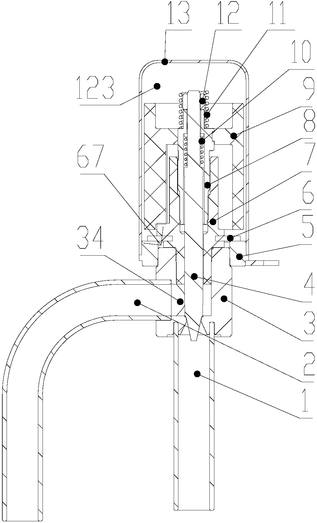
[0043] Please refer to Figure 1-Figure 6 As shown, the embodiment of the present invention provides an electronic expansion valve, including: a valve seat assembly, a nut assembly, a valve needle assembly, a rotor assembly and a bushing assembly.

[0044] The valve seat assembly includes a valve seat 3 , a first connecting pipe 2 connected to one side of the valve seat 3 , a second connecting pipe 1 connected to the lower part of the valve seat, and a sleeve seat 5 arranged on the valve seat 3 .

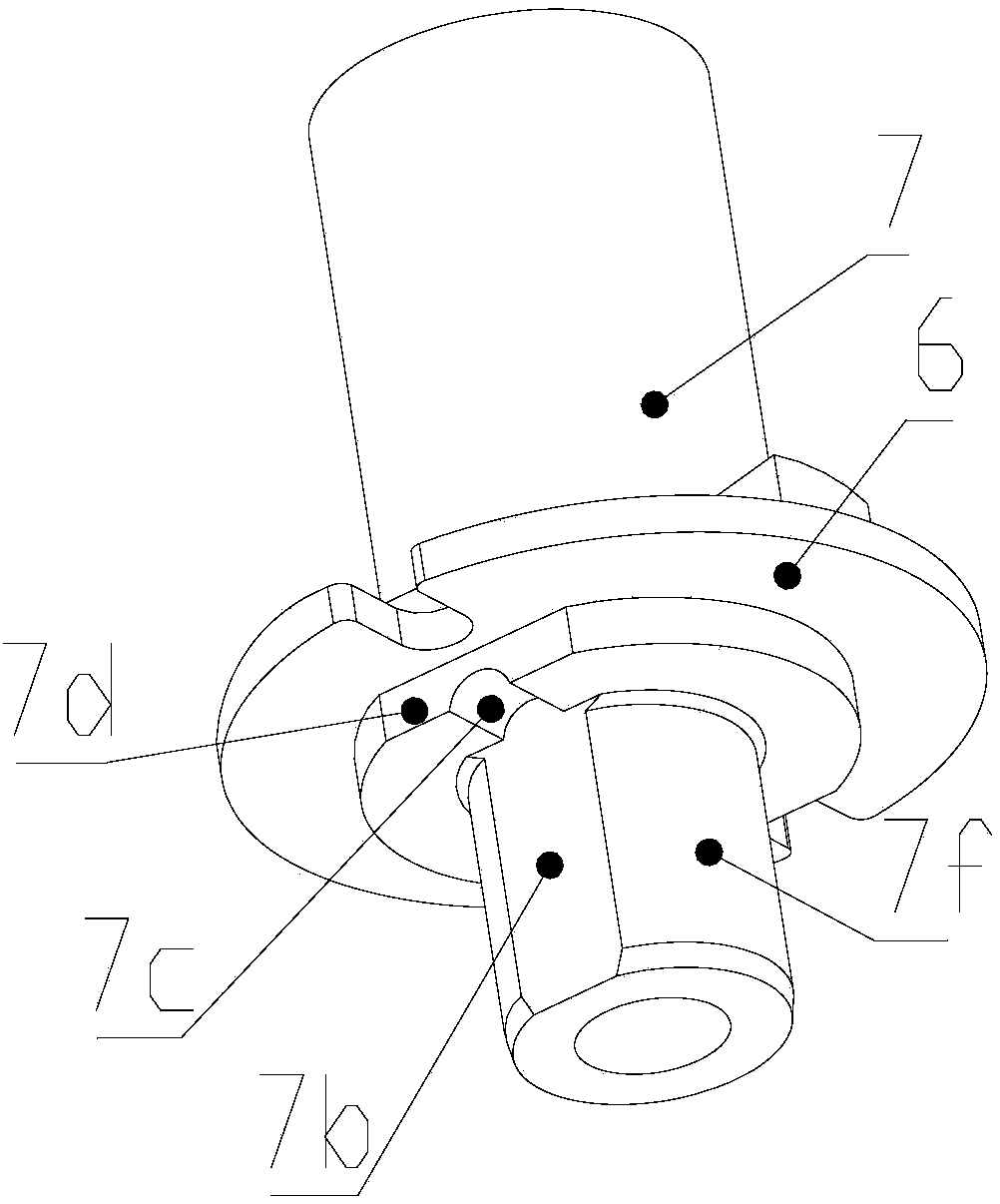
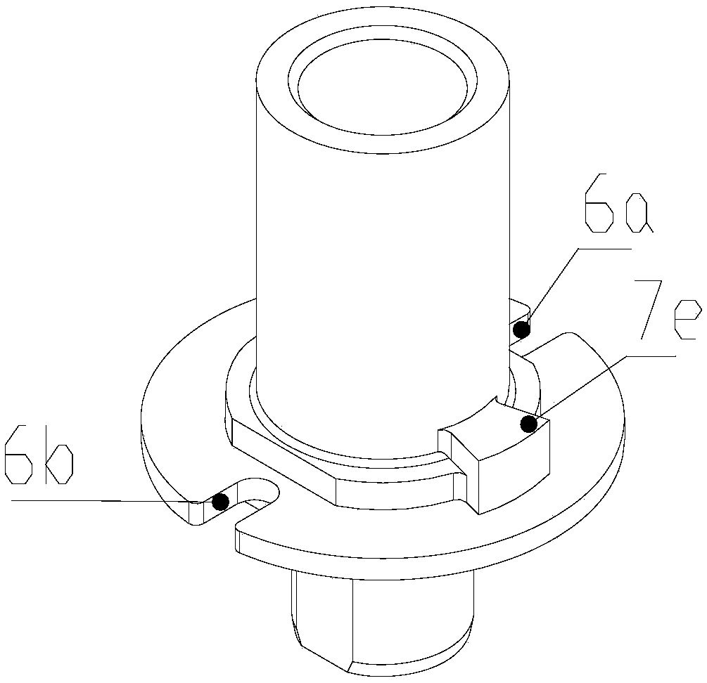
[0045] The nut assembly includes a nut 7 and a connecting plate 6 arranged on the outer ring of the middle section of the nut 7 . The connecting plate 6 is welded on the casing seat 5 . At least one first plate notch 6b is provided on the connecting plate 6, and the second plate notch 6a may also be provided, and of cou...


PUM


Abstract

The invention provides an electronic expansion valve. The electronic expansion valve includes a valve seat assembly, a nut assembly, a valve needle assembly, a rotor assembly and a sleeve assembly. The valve seat assembly includes a valve seat, a first connecting pipe connected one side of the valve seat, a second connecting pipe connected to the lower part of the valve seat and a sleeve seat disposed on the valve seat. The nut assembly includes a nut and a connecting plate disposed on the outer ring of the nut, and the connecting plate is provided with at least one first plate notch. The rotor assembly includes a magnetic rotor nested outside the nut and a screw. The joint between the first connecting pipe and the valve seat includes a first cavity, and the sleeve internally includes a second cavity. Nut notches corresponding to the first plate notches are formed in the exterior of the nut. The first plate notches and the nut notches constitute a connecting passage of the first cavityand the second cavity. The pressure between the first cavity and the second cavity can be quickly adjusted by arranging the nut notches, corresponding to the first plate notches in the connecting plate, in the exterior of the nut, so that the flow accuracy of the entire electronic expansion valve is improved.

Description

technical field [0001] The invention relates to the technical field of fluid control components, in particular to an electronic expansion valve for controlling the flow direction and flow of refrigerant. Background technique [0002] The electronic expansion valve used to adjust the flow of refrigerant in refrigeration systems such as air conditioners includes valve body parts and coils. The valve needle opening and closing degree in the valve body parts is driven by the coil to adjust the flow rate of refrigerant in the refrigeration system, so as to achieve temperature control. Effect. [0003] The valve body is generally equipped with two cavities, the flow channel cavity and the volume cavity. The flow channel cavity is connected with the inlet pipe and the outlet pipe respectively. It is a channel for fluid flow when the valve body is working. The cavity formed by the casing contains rotor parts, nut parts and other structures. Due to the precise structure of the drivi...

Claims


Application Information

Patent Timeline
Patent Type & Authority Applications(China)
IPC IPC(8): F16K1/02F16K1/32F16K1/42F16K31/50F25B41/06F25B41/34
CPCF16K1/02F16K1/32F16K1/42F16K31/50F25B2600/2513F25B41/31Y02B30/70
Inventor 陈勇好王冠军刘曈晖
Owner ZHEJIANG DUNAN MASCH CO LTD
Why Eureka
Try Eureka