Nuclear magnetic flow meter and method for operation of nuclear magnetic flow meters

a flow meter and nuclear technology, applied in the direction of liquid/fluent solid measurement, volume/mass flow by differential pressure, reradiation, etc., can solve the problem of affecting the measurement accuracy, nuclear magnetic flow meter, test separator, etc., and achieve the effect of improving the accuracy of the flow rate measuremen

Active Publication Date: 2014-05-15
KRONE GMBH
View PDF19 Cites 1 Cited by
  • Summary
  • Abstract
  • Description
  • Claims
  • Application Information

AI Technical Summary

Benefits of technology

[0008]A primary object of this invention is, therefore, to devise a nuclear magnetic flow meter with improved accuracy of th

Problems solved by technology

It follows from this that, in nuclear magnetic flow meters, the measurement accuracy for the measurement of the liquid phase of the medium can be relatively accurate, while the smaller magnitude of the electrical signals for the gaseous phases adversely affects the measurement accuracy of the nuclear magnetic flow meters for the measurement of the gaseous phase, especially when the gaseous phase has a relatively low density and/or when the gaseous phase

Method used


Image

  • Nuclear magnetic flow meter and method for operation of nuclear magnetic flow meters
  • Nuclear magnetic flow meter and method for operation of nuclear magnetic flow meters
  • Nuclear magnetic flow meter and method for operation of nuclear magnetic flow meters

Examples


Embodiment Construction

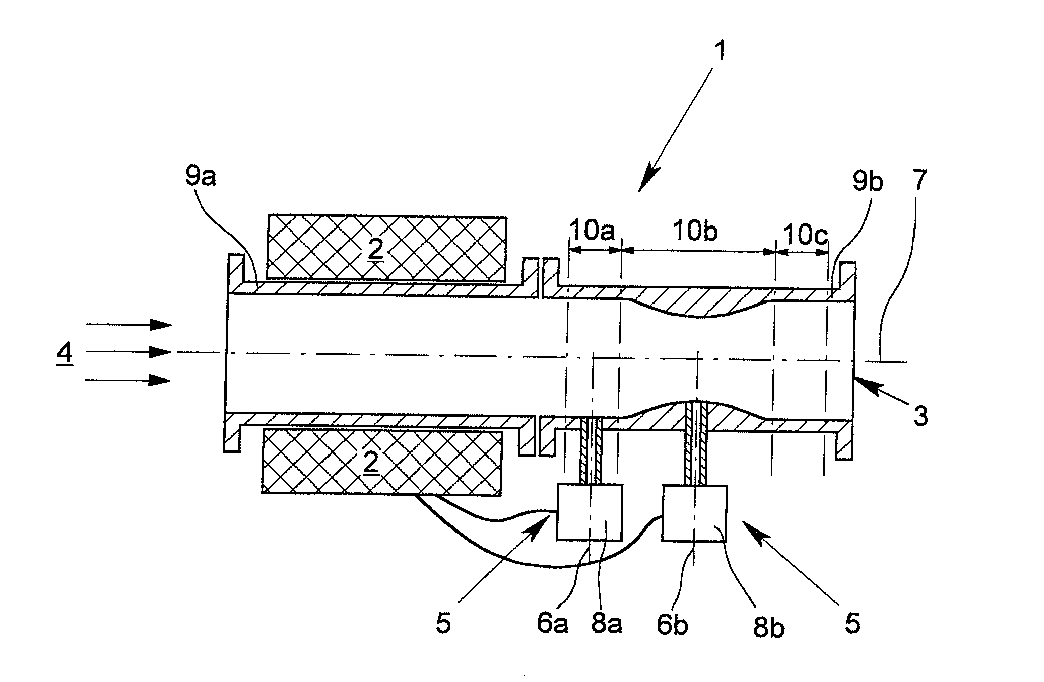
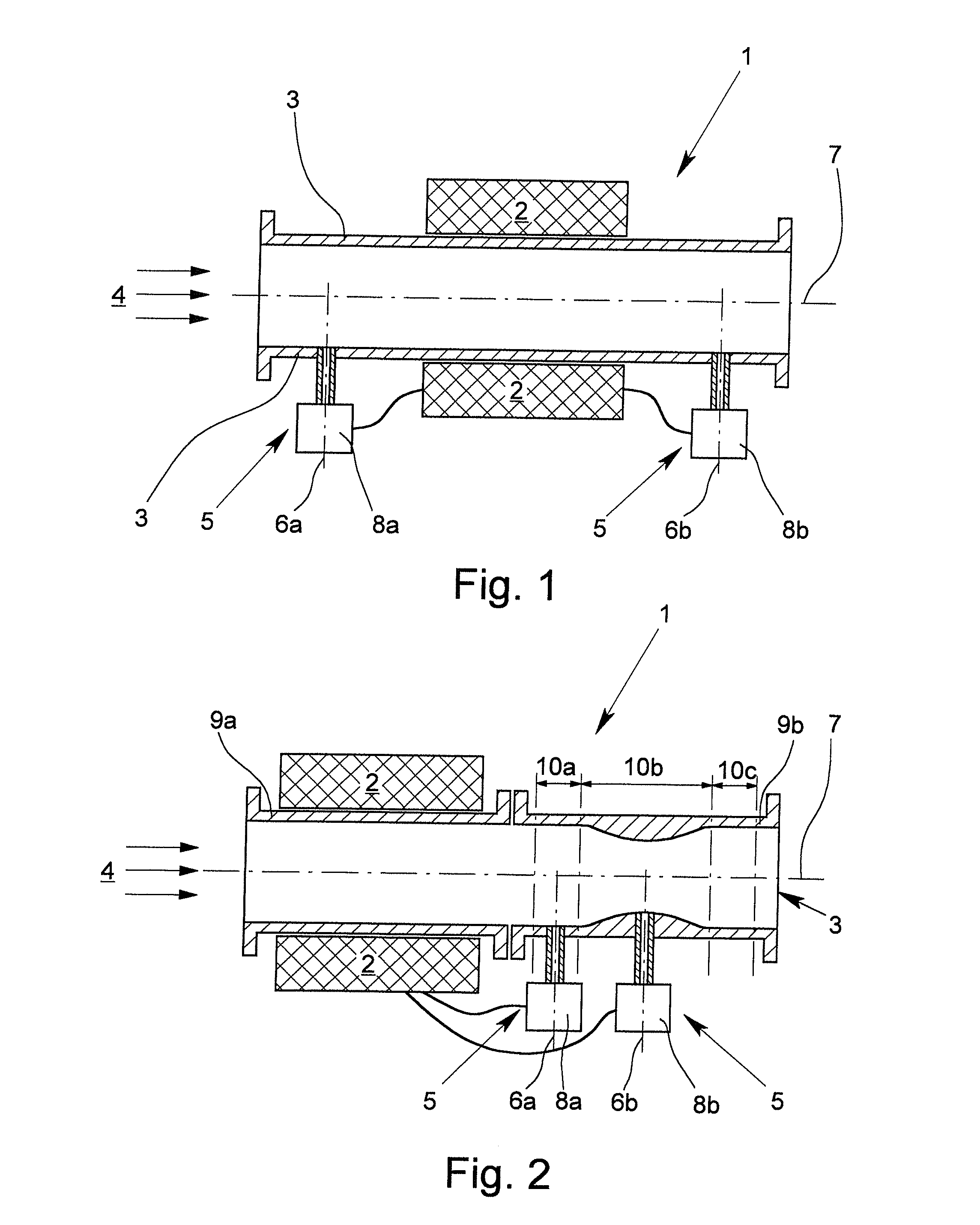
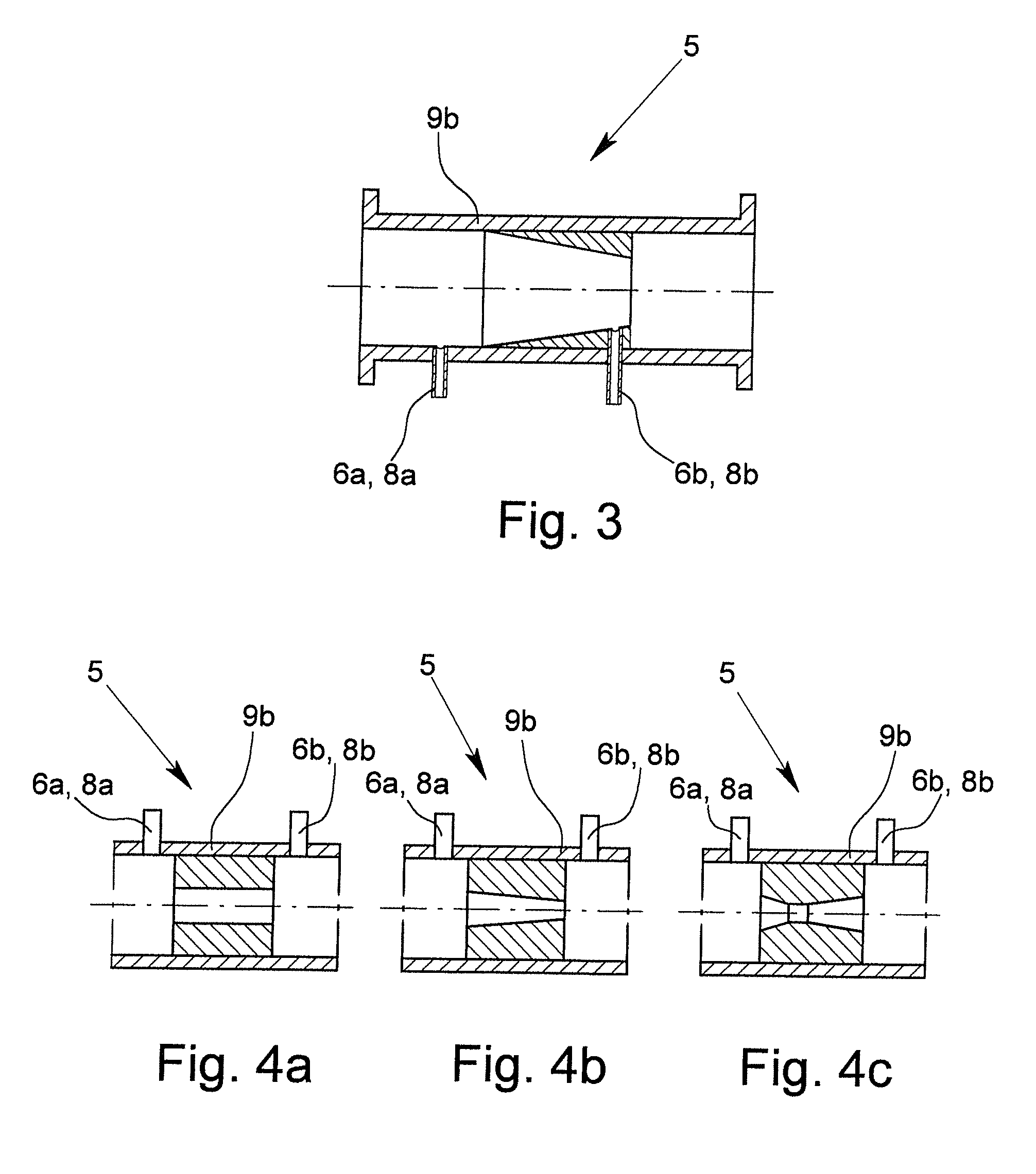
[0030]FIG. 1 schematically shows a first exemplary embodiment and FIG. 2 shows a second exemplary embodiment of the nuclear magnetic flow meter 1 in accordance with the invention. Each of the nuclear magnetic flow meters 1 comprises a nuclear magnetic measurement device 2 for measuring the flow rate of a multiphase medium 4 which is flowing through a measuring tube 3. The nuclear magnetic measurement device 2 is located around the measuring tube 3. In addition, there is an additional measurement device which works according to a measurement principle other than the nuclear magnetic measurement principle. In both exemplary embodiments, the other measurement device is a differential pressure flow rate measurement device 5. Here, the differential pressure flow rate measurement device 5 has a pressure gauge 8a, 8b at each of two longitudinal sites 6a, 6b which are spaced from each other in the longitudinal direction 7 of the measuring tube 3.

[0031]Both in the first exemplary embodiment ...


PUM


Abstract

A nuclear magnetic flow meter (1) for measuring the flow rate of a multiphase medium (4) which is flowing through a measuring tube (3) is described, with a nuclear magnetic measurement device (2), the nuclear magnetic measurement device (2) being located around the measuring tube (3).
In accordance with the invention an improved accuracy of the measurement of the flow rate for the gaseous phase is achieved in that in addition to the nuclear magnetic measurement device (2) there is a further measurement device which implements another measurement principle, in the described exemplary embodiment a differential pressure flow rate measurement device (5). In the described exemplary embodiment the differential pressure flow rate measurement device (5) is made for measuring the differential pressure of the medium (4) in the measuring tube (3), and there are at least one pressure gauge (8a, 8b) each on two measurement sites (6a, 6b) which are different in the longitudinal direction (7) of the measuring tube (3).

Description

BACKGROUND OF THE INVENTION[0001]1. Field of the Invention[0002]The invention relates to a nuclear magnetic flow meter for measuring the flow rate of a multiphase medium which is flowing through a measuring tube, with a nuclear magnetic measurement device, the nuclear magnetic measurement device being located around the measuring tube. Moreover, the invention also relates to a method for operation of nuclear magnetic flow meters.[0003]2. Description of Related Art[0004]The atomic nuclei of the elements which have a nuclear spin also have a magnetic moment which is caused by the nuclear spin. The nuclear spin can be construed as an angular momentum described by a vector, and accordingly the magnetic moment can also be described by a vector which is aligned parallel to the vector of the angular momentum. The vector of the magnetic moment of an atomic nucleus in the presence of a macroscopic magnetic field is aligned parallel to the vector of the macroscopic magnetic field at the locat...

Claims


Application Information

Patent Timeline
IPC IPC(8): G01F1/716
CPCG01F1/716G01F1/44G01F1/74
Inventor HOGENDOORN, CORNELIUS JOHANNES
Owner KRONE GMBH
Why Eureka
Try Eureka