Gas flowmeter

a flowmeter and gas technology, applied in the direction of volume/mass flow measurement, measurement devices, instruments, etc., can solve the problems of insufficient durability of sealing materials, leakage of gas between bolts and periphery holes formed in device bodies, and inability to perform stable flow rate measurement, etc., to achieve enhanced accuracy of flow rate measurement and suppress vibration of ultrasonic flow rate measuring units

Active Publication Date: 2019-12-24
PANASONIC INTELLECTUAL PROPERTY MANAGEMENT CO LTD
View PDF20 Cites 1 Cited by
  • Summary
  • Abstract
  • Description
  • Claims
  • Application Information

AI Technical Summary

Benefits of technology

[0008]The present invention has been made to overcome the drawbacks of the conventional art, and it is an object of the present invention to enhance accuracy of flow rate measurement in a gas flowmeter having an ultrasonic flow rate measuring unit and a flow passage.
[0010]According to the gas flowmeter of the present invention, vibrations of the ultrasonic flow rate measuring unit can be suppressed and hence, accuracy of flow rate measurement can be enhanced.

Problems solved by technology

This swinging of ultrasonic flow rate measuring unit 108 gives rise to a drawback that stable flow rate measurement cannot be performed.
However, durability of the sealing material is not sufficient compared to a life of a gas meter.
Accordingly, there is a drawback that leakage of a gas occurs between the bolt and the periphery of the hole formed in device body 101 when the sealing material is peeled off.

Method used


Image

  • Gas flowmeter
  • Gas flowmeter
  • Gas flowmeter

Examples


first exemplary embodiment

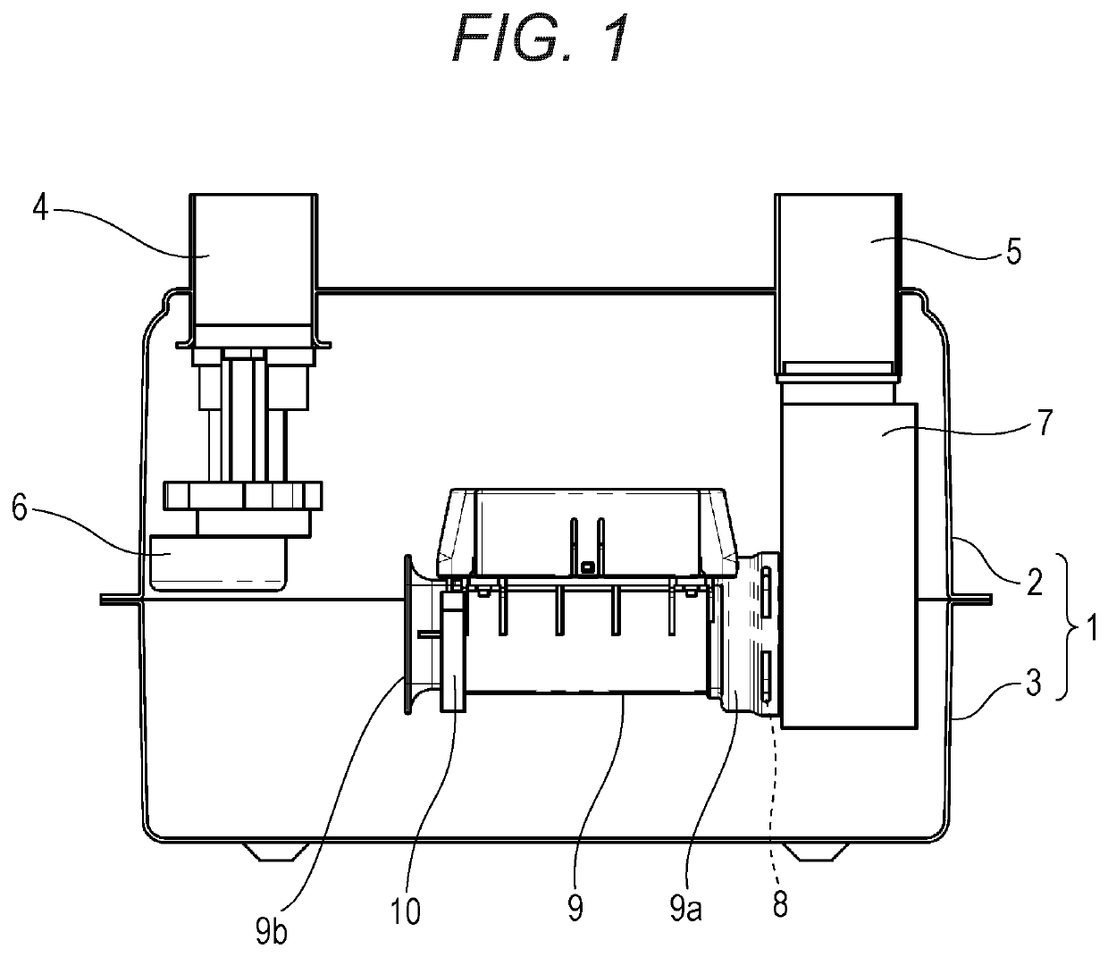
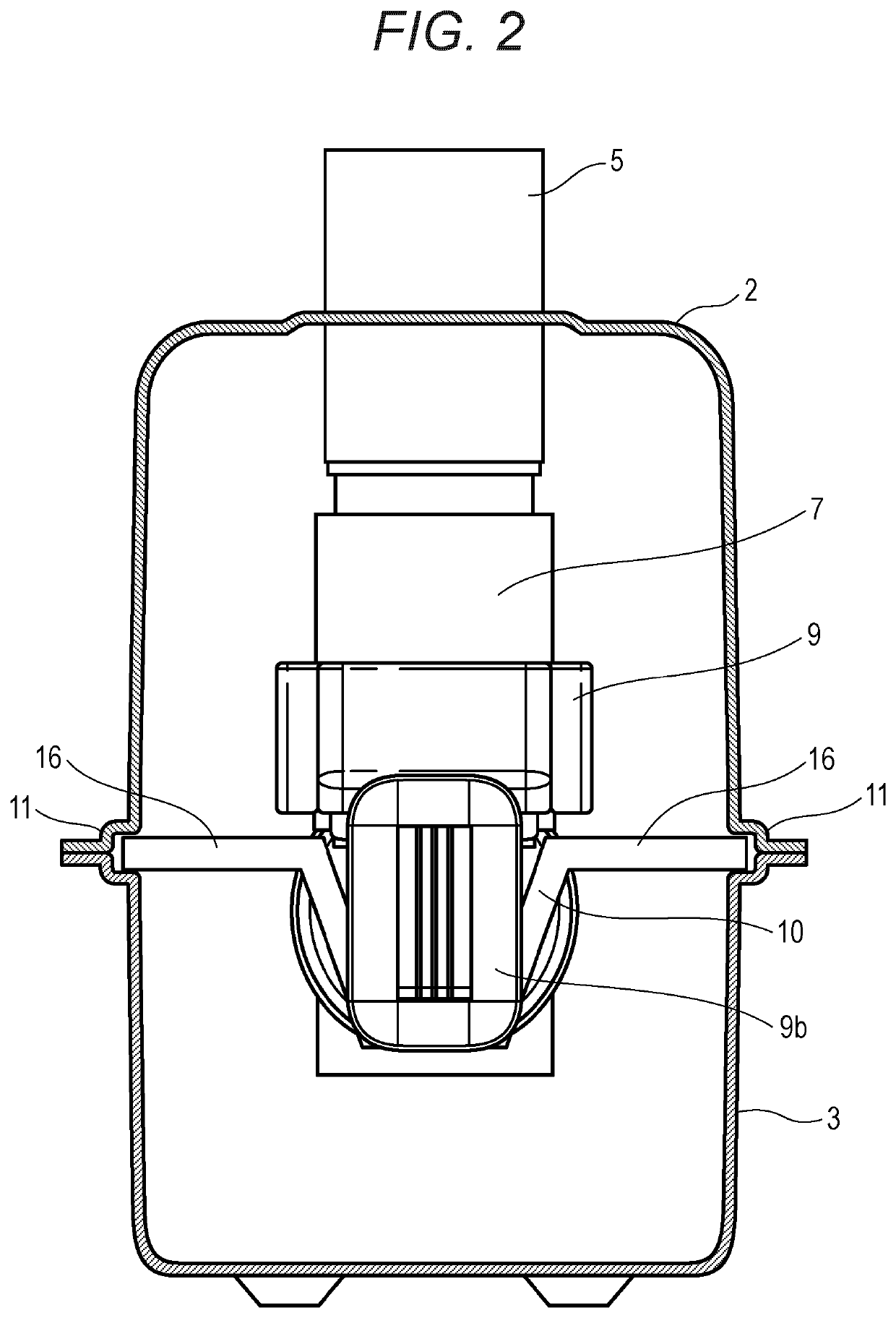
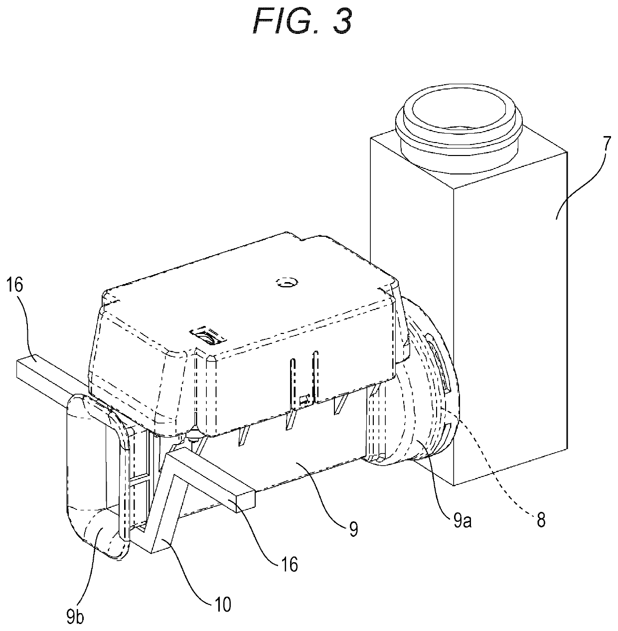
[0054]FIG. 1 is a side view of a gas flowmeter according to a first exemplary embodiment of the present invention. FIG. 2 is a cross-sectional view of the gas flowmeter as viewed in another direction. FIG. 3 is a perspective view of a main part of the gas flowmeter. FIG. 4 is an enlarged cross-sectional view of the main part of the gas flowmeter. FIG. 5 is a perspective view of the main part of the gas flowmeter. FIG. 6 is a perspective view of a support member of the gas flowmeter.

[0055]An outer shell of the gas flowmeter is configured by device body 1. Device body 1 air-tightly accommodates a gas (fluid to be measured) therein. Device body 1 is configured by upper case 2 and lower case 3 formed by performing press working on metal. Inlet pipe 4 and outlet pipe 5 are disposed on an upper surface of upper case 2. Inlet pipe 4 opens in the inside of device body 1 through cut-off valve 6. A fluid to be measured flows into device body 1 through inlet pipe 4. Connecting pipe 7 is connec...

second exemplary embodiment

[0071]Hereinafter, the second exemplary embodiment of the present invention is described with reference to FIG. 7 to FIG. 11. Parts having an identical configuration with the corresponding parts of the first exemplary embodiment are given same symbols and the description of these parts is omitted.

[0072]FIG. 7 is a cross-sectional view of a gas flowmeter according to the second exemplary embodiment of the present invention. FIG. 8 is a cross-sectional view of a main part of the gas flowmeter. FIG. 9 is a perspective view of a main part of the gas flowmeter. FIG. 10 is a perspective view of the main part of the gas flowmeter. FIG. 11 is a perspective view of a support member of the gas flowmeter.

[0073]In the second exemplary embodiment, ultrasonic flow rate measuring unit 17 has locking projections 18 on lower portions of both side surfaces thereof on an inflow port 17b side. Support member 19 has fixing portion 20 on a center portion thereof, and has locking pawls 21 on a left side a...

third exemplary embodiment

[0081]Hereinafter, the third exemplary embodiment of the present invention is described with reference to FIG. 12 to FIG. 16. Parts having an identical configuration with the corresponding parts of the first exemplary embodiment or the second exemplary embodiment are given same symbols and the description of these parts is omitted.

[0082]FIG. 12 is a cross-sectional view of a gas flowmeter according to the third exemplary embodiment of the present invention. FIG. 13 is a cross-sectional view of a main part of the gas flowmeter. FIG. 14 is a perspective view of a main part of the gas flowmeter. FIG. 15 is a perspective view of the main part of the gas flowmeter. FIG. 16 is a perspective view of a support member of the gas flowmeter.

[0083]In the third exemplary embodiment, ultrasonic flow rate measuring unit 23 has locking recessed portions 24 on lower portions of both side surfaces thereof on an inflow port 23b side. Support member 25 has fixing portion 26 on a center portion thereof,...


PUM


Abstract

A gas flowmeter includes: device body (1) which accommodates a fluid to be measured; inlet pipe (4) through which the fluid to be measured flows into device body (1); and outlet pipe (5) through which the fluid to be measured flows out from device body (1) through connecting pipe (7). The gas flow meter also includes: ultrasonic flow rate measuring unit (9) which has a first end side connected to outlet pipe (5) and performs flow rate measurement of the fluid to be measured which flows in ultrasonic flow rate measuring unit (9); and connecting pipe (7) which is disposed between ultrasonic flow rate measuring unit (9) and outlet pipe (5), and is connected to outlet pipe (5). The gas flow meter further includes support member (10) which supports a second end side of ultrasonic flow rate measuring unit (9).

Description

TECHNICAL FIELD[0001]The present invention relates to a gas flowmeter for measuring a flow rate of a gas.BACKGROUND ART[0002]A gas flowmeter measures a flow rate of a gas (fluid to be measured) in such a manner that an ultrasonic wave is propagated through a gas which flows in a measuring pipe provided to a middle portion of a gas flow passage. For example, the gas flowmeter measures a flow rate of a gas by making use of a propagation time of an ultrasonic wave or a propagation speed of an ultrasonic wave.[0003]FIG. 42 is a side view of a conventional gas flowmeter. Device body 101 is configured by upper case 102 and lower case 103 which are formed by performing press working on metal. Inlet pipe 104 and outlet pipe 105 are disposed on upper case 102. Inlet pipe 104 opens in the inside of device body 101 through cut-off valve 106. Ultrasonic flow rate measuring unit 108 is connected to outlet pipe 105 through L-shaped connecting pipe 107.[0004]However, in the conventional configurat...

Claims


Application Information

Patent Timeline
Patent Type & Authority Patents(United States)
IPC IPC(8): G01F1/66G01F15/18
CPCG01F15/18G01F1/667G01F15/185G01F1/662G01F1/66
Inventor MORIHANA, HIDEAKISATOU, MASATONAGAHARA, HIDETOMOTERAJI, MASANOBUNAGANUMA, NAOTO
Owner PANASONIC INTELLECTUAL PROPERTY MANAGEMENT CO LTD
Why Eureka
Try Eureka