Method of forming a flow restriction in a fluid communication system

a technology of fluid communication system and flow restriction, which is applied in the direction of decorative arts, hollow objects, chemical vapor deposition coating, etc., can solve the problems of difficult to repeatedly manufacture flow restrictions having resistivities within the same narrow limited tolerance, and difficult to provide flow restrictions having precise and reliable flow resistivity, etc., to achieve the effect of improving the accuracy of flow resistivity

Inactive Publication Date: 2015-04-28
FLOWSION
View PDF13 Cites 1 Cited by
  • Summary
  • Abstract
  • Description
  • Claims
  • Application Information

AI Technical Summary

Benefits of technology

[0005]It is, thus, an object of the invention to provide a method of forming a flow restriction in a fluid communication system, wherein the accuracy of the flow resistivity is improved as compared to prior art methods.
[0006]It is a further object of the invention to provide a method of forming a flow restriction in a fluid communication system, wherein the manufacturing costs can be reduced as compared to prior art methods.
[0007]It is an even further object of the invention to provide a method of forming a flow restriction in a microfluidic system, wherein a high accuracy of the flow resistivity is obtained while maintaining low manufacturing costs.
[0015]When forming a flow restriction in accordance with the method of the present invention, a flow restricting section having a cross sectional area and a length is initially provided. At this stage it is not necessary to obtain an accurate flow resistivity, as will be explained further below. Therefore the flow restricting section may be formed using manufacturing techniques with relatively high tolerances, and it is therefore possible to use techniques which are cost effective, and the manufacturing costs can thereby be minimised.
[0018]Thus, the present invention combines the use of a cost effective, but inaccurate, manufacturing method with a ‘fine tuning step’ providing the desired accuracy to the flow resistivity. Thereby the flow restriction can be manufactured with low manufacturing costs as well as high accuracy. This is very desirable.

Problems solved by technology

In microfluidic systems it is very difficult to provide flow restrictions having a precise and reliable flow resistivity, since the small dimensions of microfluidic systems increases the requirements to the manufacturing tolerances of the flow restrictions.
Accordingly, it is difficult to repeatedly manufacture flow restrictions having resistivities within the same narrow limited tolerances.

Method used


Image

  • Method of forming a flow restriction in a fluid communication system
  • Method of forming a flow restriction in a fluid communication system
  • Method of forming a flow restriction in a fluid communication system

Examples


second embodiment

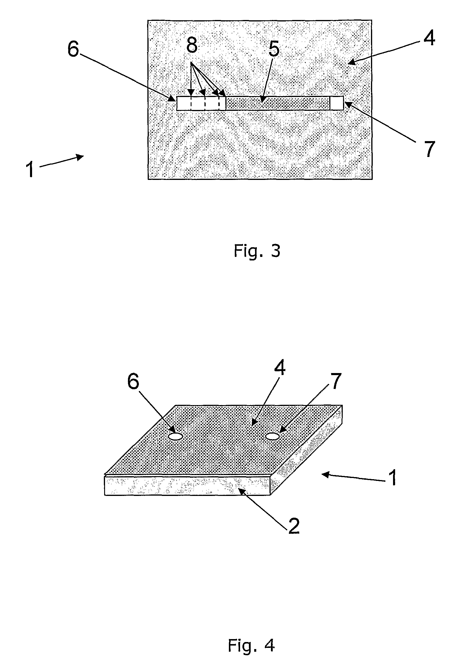
[0051]FIG. 5 is a perspective view of a flow restrictor system 1 formed by means of a method according to the invention. The flow restrictor system 1 of FIG. 5 comprises two substrates 2, each having a groove 3 formed in a substantially planar surface thereof. The substrates 2 are then joined together in such a manner that the grooves 3 are arranged opposite to each other, thereby forming a channel. An inlet opening and an outlet opening (not shown) are formed in one of the substrates 2. Subsequently, material is removed adjacent to the inlet opening and / or adjacent to the outlet opening, thereby decreasing the length of the channel and decreasing the flow resistivity of the flow restrictor, until a desired flow resistivity is obtained.

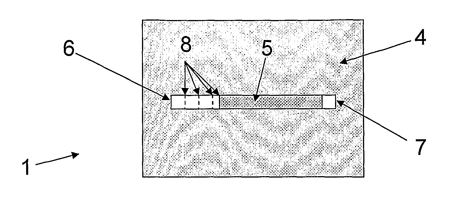
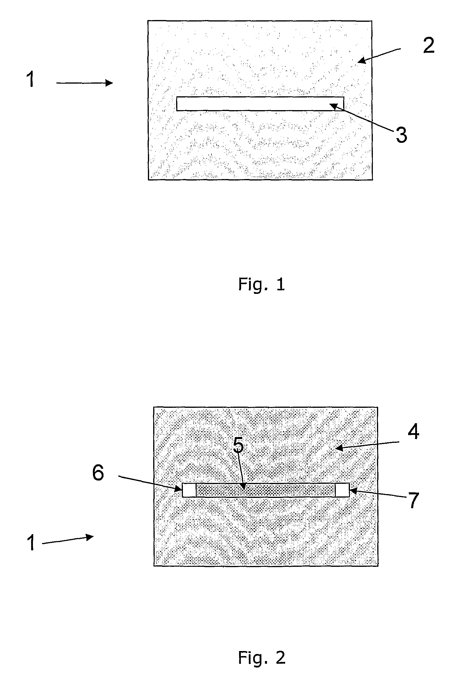
[0052]FIG. 6 shows a substrate 2 having a groove 3 formed in a substantially planar surface thereof. The groove 3 extends the entire width of the substrate 2. Accordingly, an inlet opening 6 is formed at one end part of the substrate 2, and an outlet ...

fifth embodiment

[0054]FIGS. 8A-8C illustrate the method of the invention. According to this embodiment the groove is split into two grooves 3a, 3b arranged in parallel with a separating wall 11 there between. The parallel section of the grooves 3a, 3b defines a length 12. In FIG. 8A the grooves 3a, 3b are completely separated.

[0055]In FIG. 8B a part 13a of the separating wall 11 has been removed, thereby forming a passage between the grooves 3a, 3b and decreasing the length 12. As a consequence, the flow resistivity of the flow restrictor is decreased.

[0056]In FIG. 8C a larger part 13b of the separating wall 11 has been removed. Thereby the length 12, as well as the flow resistivity of the flow restrictor, has been further decreased.

[0057]Thus, according to the method illustrated in FIGS. 8A-8C, the flow resistivity is adjusted by removing a part of the separating wall 11, thereby reducing the length 12.

[0058]FIG. 9 shows a substrate 2 in which a groove 3 has been formed. Subsequently, material has...


PUM

PropertyMeasurementUnit
widthaaaaaaaaaa
widthaaaaaaaaaa
lengthaaaaaaaaaa

Abstract

A method of forming a flow restriction in a fluid communication system is disclosed. The method comprises the steps of providing a flow restricting section having a cross sectional area and a length, measuring the flow resistivity of the flow restricting section, and modifying the cross sectional area and / or the length of the flow restricting section until a desired flow resistivity of the flow restricting section is obtained. The method provides the possibility of forming a flow restriction in an easy and cost effective manner, and to subsequently adjust the flow resistivity of the flow restriction, thereby obtaining an accurate flow resistivity.

Description

CROSS REFERENCE TO RELATED APPLICATIONS[0001]This application is entitled to the benefit of and incorporates by reference essential subject matter disclosed in International Patent Application No. PCT / DK2009 / 000217 filed on Oct. 7, 2009 and Danish Patent Application No. PA 2008 01414 filed on Oct. 8, 2008.FIELD OF THE INVENTION[0002]The present invention relates to a method of forming microfluidic flow restrictions in flow systems, the flow restrictions having a correct and desired flow resistivity.BACKGROUND OF THE INVENTION[0003]When providing flow restrictions in flow systems it is most often desirable to ensure that the obtained flow resistivity is precise and at a desired value, since this adds to the reliability of the flow system. In microfluidic systems it is very difficult to provide flow restrictions having a precise and reliable flow resistivity, since the small dimensions of microfluidic systems increases the requirements to the manufacturing tolerances of the flow restr...

Claims


Application Information

Patent Timeline
Patent Type & Authority Patents(United States)
IPC IPC(8): B23P17/00B81C1/00F16K99/00
CPCF16K99/0001B81C1/00119F16K99/0021B01L2400/0633B81B2201/054Y10T29/494
Inventor POULSEN, KRISTIAN RAABYRASMUSSEN, PETER ANDREAS
Owner FLOWSION
Why Eureka
Try Eureka