Pot rack of stove and stove

A cooker and pot holder technology, which is applied in the cooker field, can solve the problems of increased temperature of cooker knobs, user burns, safety hazards, etc., and achieves the effects of reducing manufacturing costs, simplifying manufacturing processes, and reducing assembly difficulty.

Pending Publication Date: 2019-07-02
BSH ELECTRICAL APPLIANCES JIANGSU +1
View PDF7 Cites 1 Cited by
  • Summary
  • Abstract
  • Description
  • Claims
  • Application Information

AI Technical Summary

Problems solved by technology

[0003] However, there are generally many disadvantages in the pot supports of the existing cookers. During the user's use, a considerable part of the heat generated by the burner (also called the stove end) of the cooker will be radiated into the air, and it has not been fully utilized for cooking utensils. heating, resulting in low thermal efficiency of the cooker
[0004] On the other hand, the design of the pot support of the existing cooker causes the burner to be directly exposed to the air, and the heat radiated from the burner will cause the temperature rise of the cooker knob to be too high, resulting in burns to the user
[0005] In addition, the design of the pot support of the existing cooker causes the burner to be exposed to the air too much, and it is very easy to be affected by the wind during use and cause the flame to extinguish or scatter, causing serious safety hazards
[0006] At this stage, in most cases, it is impossible to provide a more suitable pot support for the stove, which can achieve the effect of wind and fire protection while gathering heat

Method used


Image

  • Pot rack of stove and stove
  • Pot rack of stove and stove
  • Pot rack of stove and stove

Examples


Embodiment Construction

[0051] As mentioned in the background art, the pot racks used in existing cookers generally cannot effectively collect heat, and the effects of wind and fire protection are not ideal.

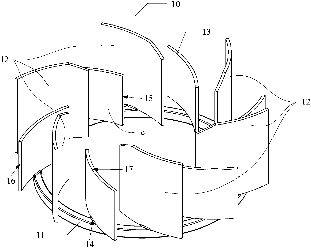
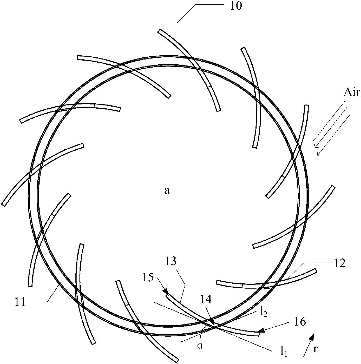
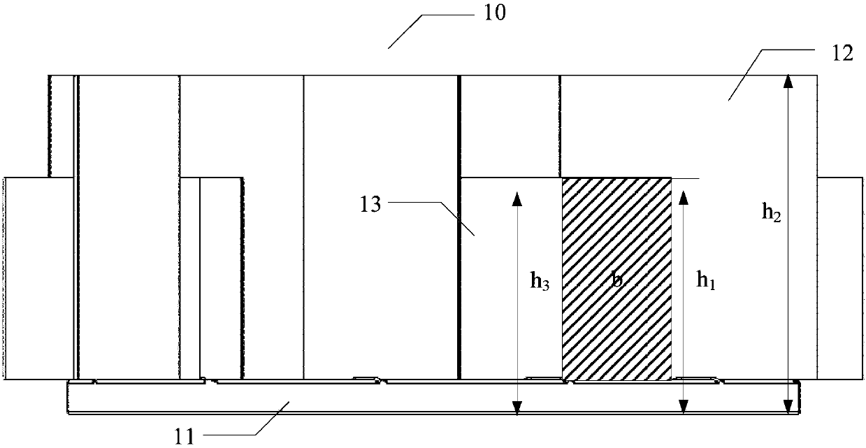
[0052] In order to solve the above technical problems, an embodiment of the present invention provides a pan support for a cooker, which includes a bottom frame and at least three support feet for supporting cooking utensils, and also includes: a plurality of baffles, the plurality of baffles are arranged on The bottom frame is used to surround the combustion area located in the bottom frame when the pan support is in use, wherein each baffle plate has a mounting contact point on the bottom frame, and the baffle plate is located on the bottom frame. There is an included angle α between the tangent line on the installation contact point and the tangent line of the bottom frame on the installation contact point, and the value range of the included angle α is 0°<α<90°. A first end of the plate ext...


PUM


Abstract

The invention discloses a pot rack of a stove and the stove. The pot rack of the stove comprises a bottom frame and at least three supporting legs for supporting a cooking utensil; the pot rack further comprises a plurality of baffles, the baffles are arranged on the bottom frame so as to surround a combustion area located in the bottom frame in the using state of the pot rack. Each baffle plate is provided with a mounting contact point on the bottom frame; an included angle alpha is formed between the tangent line of each baffle on the mounting contact point and the tangent line of the bottomframe on the mounting contact point, wherein the included angle alpha is greater than 0 degree and less than 90 degrees; the first end of each baffle extends to the interior of the bottom frame fromthe corresponding mounting contact point, and the second end of each baffle extends to the exterior of the bottom frame from the mounting contact point. According to the scheme provided by the invention, air circulation can be promoted while the heat efficiency is improved, and the wind shielding effect and the fire avoiding effect of a stove knob are achieved.

Description

technical field [0001] The invention relates to the technical field of cooker, in particular to a pot support and the cooker. Background technique [0002] A stove, as an indispensable kitchen utensil in people's daily life, provides heat for the cooking utensils during the cooking process of the user, and also plays a role in supporting the cooking utensils through the pan support of the stove. [0003] However, there are generally many disadvantages in the pot supports of the existing cookers. During the user's use, a considerable part of the heat generated by the burner (also called the stove end) of the cooker will be radiated into the air, and it has not been fully utilized for cooking utensils. Heat supply, resulting in low thermal efficiency of the cooker. [0004] On the other hand, the design of the pot support of the existing cooker causes the burner to be directly exposed to the air, and the heat radiated by the burner will cause the temperature rise of the cooke...

Claims


Application Information

Patent Timeline
Patent Type & Authority Applications(China)
IPC IPC(8): F24C15/10F24C15/28F24C15/36
CPCF24C15/10F24C15/101F24C15/107F24C15/28F24C15/36
Inventor 陈传文许瑞苗伟伟朱伟洪陈勇
Owner BSH ELECTRICAL APPLIANCES JIANGSU
Why Eureka
Try Eureka