Flexible linear motor double-drive gantry platform

A linear motor and gantry technology, applied in the field of machine tool bed frames, can solve the problems of increasing the friction force of the guiding mechanism, difficult to adjust the verticality of the beam, affecting the life of the guiding mechanism, etc. The effect of internal stress

Pending Publication Date: 2019-07-05
横川机器人(深圳)有限公司
View PDF0 Cites 5 Cited by
  • Summary
  • Abstract
  • Description
  • Claims
  • Application Information

AI Technical Summary

Problems solved by technology

[0002] The traditional linear motor-driven gantry structure usually adopts two vertical and one horizontal bed frame structures. The X-direction beam is rigidly fixed on two parallel Y-direction linear motor drive mechanisms. The X-direction beam can only move in the Y direction and cannot rotate. However, the above-mentioned gantry has the following disadvantages: it is affected by the machining accuracy and installation accuracy, it is difficult to adjust the verticality of the beam and the two Y directions, and if the parallelism between the two Y direction guide mechanisms is not guaranteed, the synchronous drive will not be guaranteed. Well, when the crossbeam runs, it will generate internal stress between the systems, increase the friction of the guiding mechanism, and affect the life of the guiding mechanism. Therefore, in order to solve the above technical problems, it is indeed necessary to provide an innovative flexible linear motor double-drive gantry platform , to overcome the defects in the prior art

Method used


Image

  • Flexible linear motor double-drive gantry platform
  • Flexible linear motor double-drive gantry platform
  • Flexible linear motor double-drive gantry platform

Examples


Embodiment Construction

[0018] The following will clearly and completely describe the technical solutions in the embodiments of the present invention with reference to the accompanying drawings in the embodiments of the present invention. Obviously, the described embodiments are only some, not all, embodiments of the present invention. Based on the embodiments of the present invention, all other embodiments obtained by persons of ordinary skill in the art without making creative efforts belong to the protection scope of the present invention.

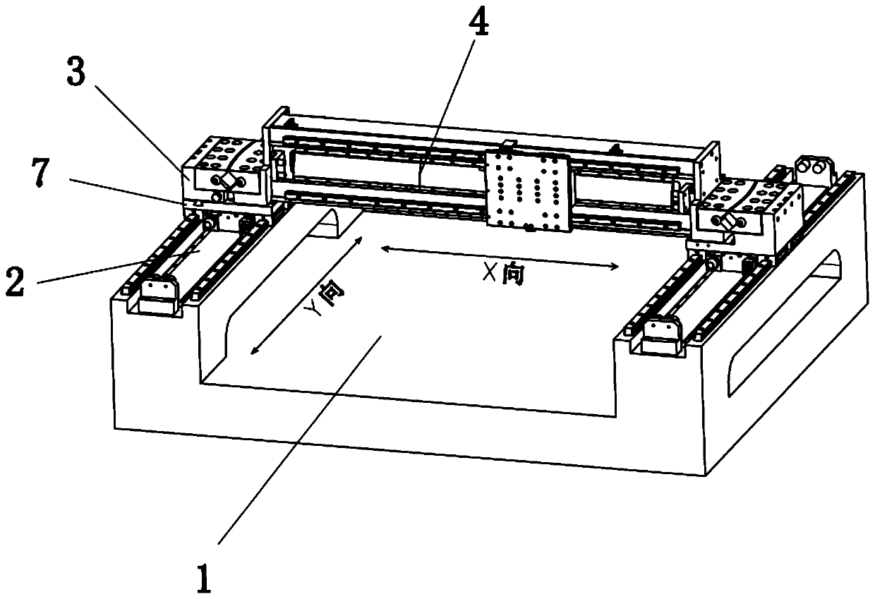
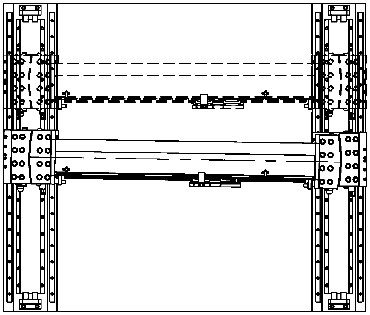
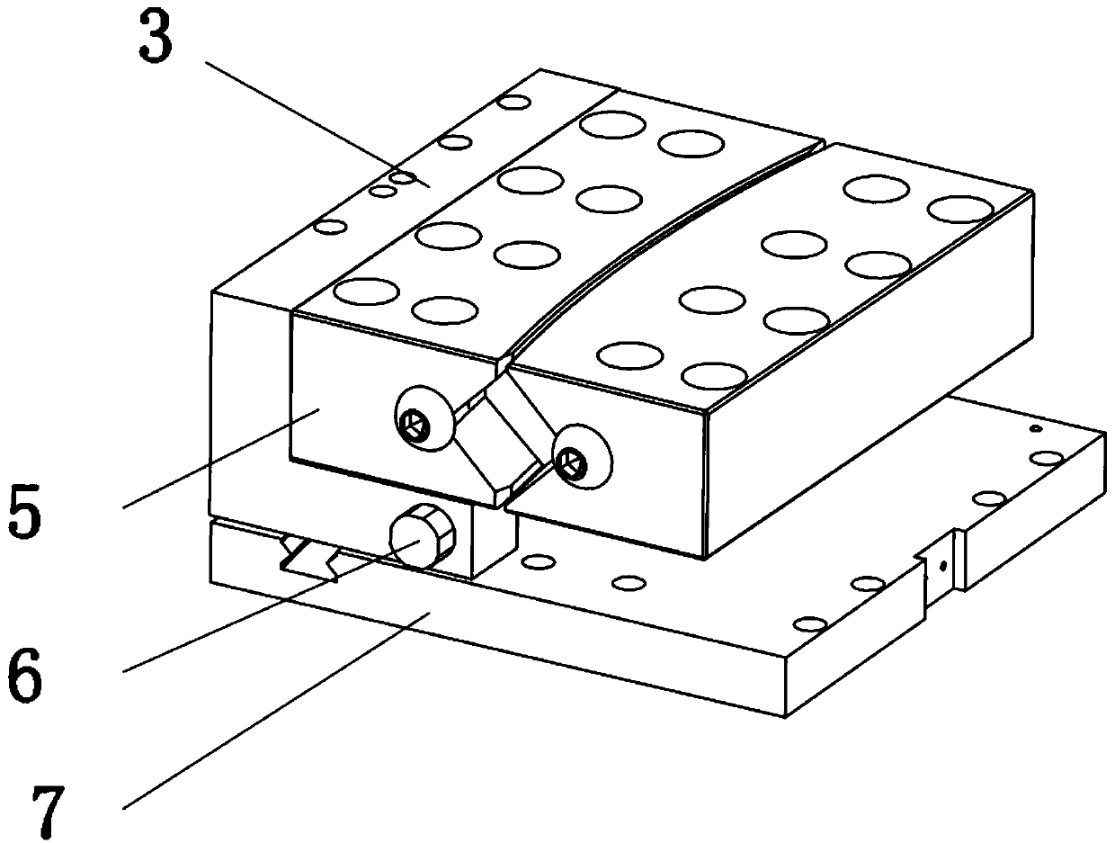
[0019] see Figure 1-5 , the present invention provides a technical solution: including a base 1, a vertical linear motor 2 is fixedly connected to the left and right sides of the top of the base 1, and the two linear motors are driven in both horizontal and vertical directions, and the tops of the two vertical linear motors 2 Both are fixedly connected with connecting plate 7, connecting plate 7 is the connecting medium, there is a chute 9 on the top left sid...


PUM


Abstract

The invention discloses a flexible linear motor double-drive gantry platform. The flexible linear motor double-drive gantry platform comprises a base, longitudinal linear motors are fixedly connectedto the left side and the right side of the top end of the base correspondingly, connecting plates are fixedly connected to the top ends of the two longitudinal linear motors, sliding grooves are formed in the top ends of the left sides of the connecting plates, supports are arranged on the top ends of the connecting plates, pulleys are arranged on the bottoms of the front ends of the supports, thepulleys are movably connected with the supports, the pulleys are clamped with sliding grooves in a sliding manner, straight cylinders are fixedly connected to the front end and the rear end of the inner portion of the right side of each support, and straight rods are inserted in the straight cylinders. According to the flexible linear motor double-drive gantry platform, the phenomenon that due tomachining and mounting, the large parallelism error between the longitudinal linear motors on the two sides is caused, and structure interior inner stress is caused is effectively removed, through changing of rotation of a transverse cross beam relative to the transverse direction, the platform can well adapt to desynchrony of the longitudinal linear motors, and the aim of removing clamping caused by desynchrony of driving of the longitudinal motors on the two sides can be achieved.

Description

technical field [0001] The invention relates to the technical field of machine tool bed frames, in particular to a flexible linear motor double-drive gantry platform. Background technique [0002] The traditional linear motor-driven gantry structure usually adopts two vertical and one horizontal bed frame structures. The X-direction beam is rigidly fixed on two parallel Y-direction linear motor drive mechanisms. The X-direction beam can only move in the Y direction and cannot rotate. However, the above-mentioned gantry has the following disadvantages: it is affected by the machining accuracy and installation accuracy, it is difficult to adjust the verticality of the beam and the two Y directions, and if the parallelism between the two Y direction guide mechanisms is not guaranteed, the synchronous drive will not be guaranteed. Well, when the crossbeam runs, it will generate internal stress between the systems, increase the friction of the guiding mechanism, and affect the li...

Claims


Application Information

Patent Timeline
Patent Type & Authority Applications(China)
IPC IPC(8): B23Q1/01B23Q5/10B23Q5/34
CPCB23Q1/015B23Q1/017B23Q5/10B23Q5/34
Inventor 刘步军
Owner 横川机器人(深圳)有限公司
Why Eureka
Try Eureka