
Multiple-working-procedure clamping installation facility capable of improving machining accuracy

A processing precision and multi-process technology, which is applied in metal processing equipment, metal processing machinery parts, positioning devices, etc., can solve the problems of increasing the labor load of staff, reducing processing accuracy, and reducing clamping accuracy, so as to improve processing accuracy and Improve work efficiency, reduce loading error and improve product quality

Inactive Publication Date: 2019-07-05
天津市臣涛精密机械设备有限公司
View PDF0 Cites 1 Cited by
  • Summary
  • Abstract
  • Description
  • Claims
  • Application Information

AI Technical Summary

Problems solved by technology

[0002] At present, the bottom surface of the spline sleeve needs to be drilled and milled during the processing process. Since these processes are completed step by step on different equipment, the workpiece needs to be clamped repeatedly, which will increase the clamping error and reduce the clamping error. The accuracy of the card will reduce the machining accuracy and increase the workload of the staff. Therefore, it is necessary to develop a new type of fixture that can complete multiple processes in one clamping.

Method used


Image

  • Multiple-working-procedure clamping installation facility capable of improving machining accuracy
  • Multiple-working-procedure clamping installation facility capable of improving machining accuracy
  • Multiple-working-procedure clamping installation facility capable of improving machining accuracy

Examples


Embodiment Construction

[0019] The embodiments of the present invention will be described in detail below in conjunction with the accompanying drawings; it should be noted that the embodiments are illustrative, not restrictive, and cannot limit the protection scope of the present invention.

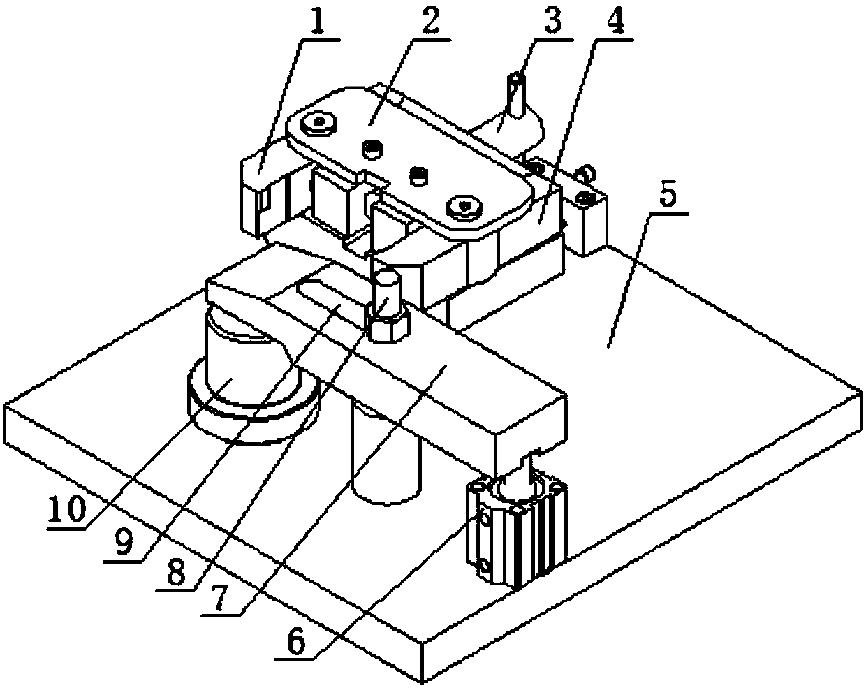
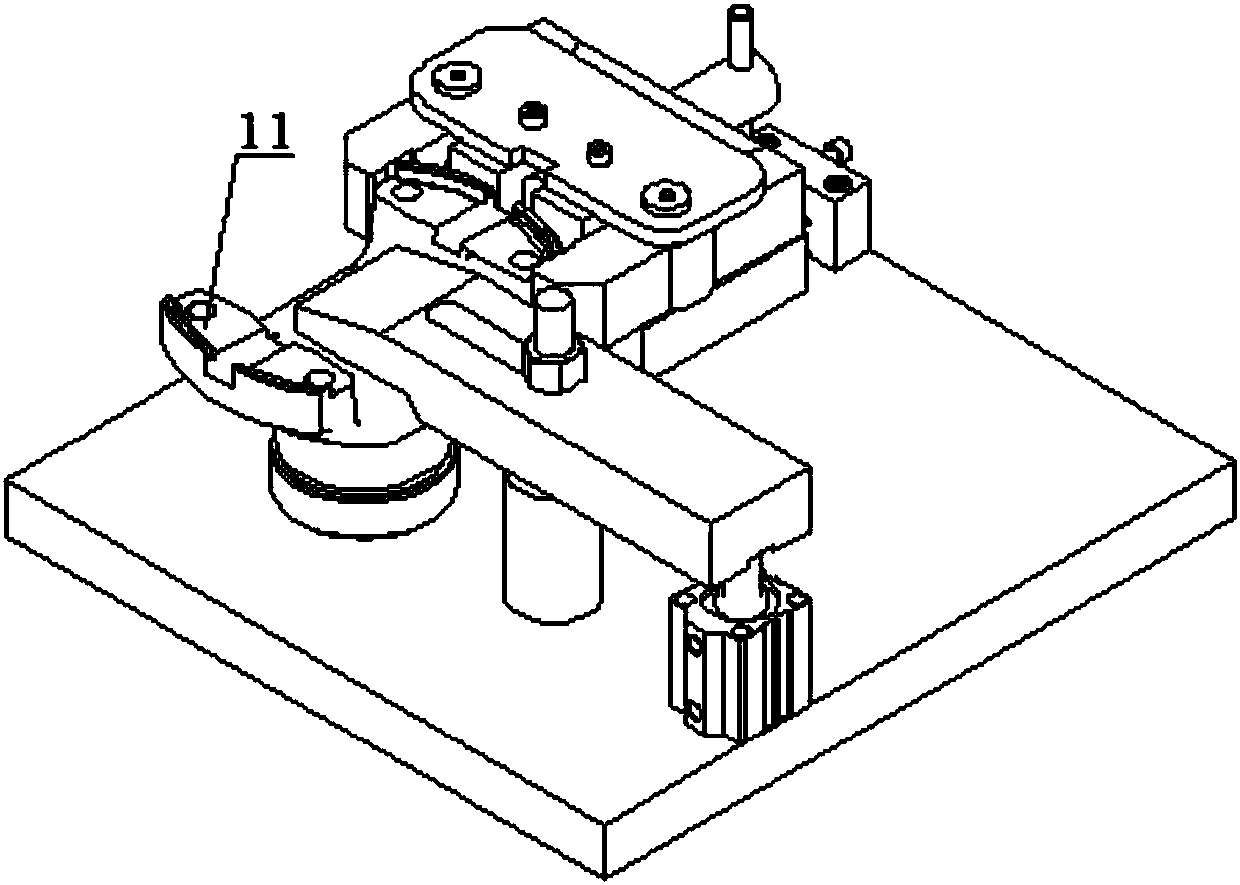
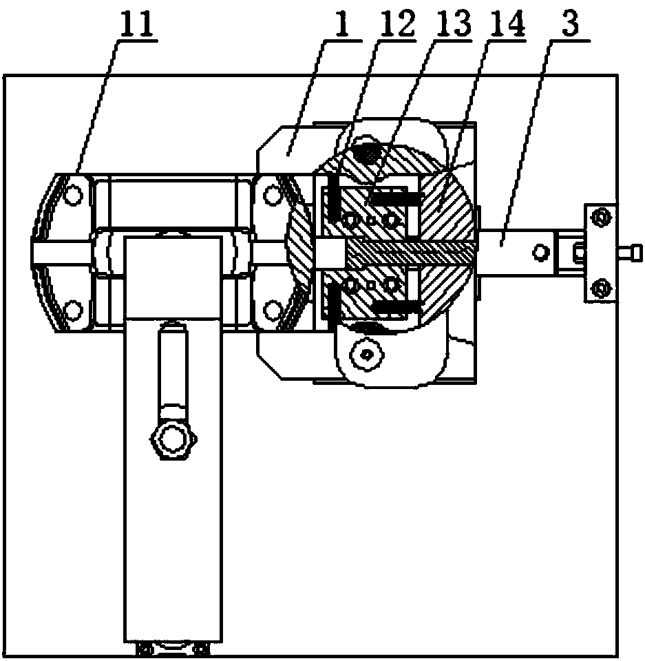
[0020] A multi-process clamping device that can improve machining accuracy, including a base plate 5, an oil cylinder 6, an upper platen 7, a mandrel 10, a linear guide rail 17, claws 1 and 4, a handle 3, and a wedge 14. The base plate can be made Mounting holes for easy installation of the device on processing equipment. An oil cylinder is installed on the upper surface of the bottom plate, and the oil cylinder is set vertically upwards. A vertical locking bar 8 is installed in the hole, and the lower end of the locking bar is installed on the base plate.

[0021] A mandrel is arranged below the front end of the pressing plate, and the mandrel is installed on the base plate. A linear guide rail is installed o...


PUM


Abstract

The invention relates to a multiple-working-procedure clamping installation facility capable of improving machining accuracy. The multiple-working-procedure clamping installation facility capable of improving the machining accuracy comprises a base plate, an oil cylinder, an upper press plate, a mandrel, a linear guide rail, clamping jaws, a handle and a wedge block. The oil cylinder is installedon the upper surface of the base plate and connected with the upper press plate, and the mandrel is arranged at the bottom of the front end of the upper press plate. The linear guide rail is installedon the portion, located on the side of the mandrel, of the base plate. A sliding pedestal is installed on the linear guide rail in a sliding mode, and the two clamping jaws are installed on the leftside and the right side of the sliding pedestal in a hinged mode correspondingly. The handle is arranged on the sliding pedestal, the wedge block is coaxially installed on the handle in a penetrativemode, and the left side wall and the right side wall of the wedge block make contact with the inner walls of the rear ends of the two clamping jaws in a press mode correspondingly. The multiple-working-procedure clamping installation facility capable of improving the machining accuracy is scientific in design, convenient to use and high in degree of automation, can be installed in a machining center and used, and can accomplish machining of multiple working procedures through one-time clamping operation, and therefore the machining accuracy and the working efficiency are greatly improved, andthe product quality is also improved.

Description

technical field [0001] The invention relates to a clamping tool in the technical field of spline sleeve processing and production, in particular to a multi-process clamping device that can improve processing accuracy. Background technique [0002] At present, the bottom surface of the spline sleeve needs to be drilled and milled during the processing process. Since these processes are completed step by step on different equipment, the workpiece needs to be clamped repeatedly, which will increase the clamping error and reduce the clamping error. The accuracy of the card will reduce the machining accuracy and increase the workload of the staff. Therefore, it is necessary to develop a new type of fixture that can complete multiple processes in one clamping. Contents of the invention [0003] The purpose of the present invention is to make up for the deficiencies of the prior art, and to provide a multi-process snap-fitting device with scientific design, reasonable structure a...

Claims


Application Information

Patent Timeline
IPC IPC(8): B23Q3/08
CPCB23Q3/062B23Q3/082
Inventor 崔越崔文来王金鹏崔建涛崔雅臣崔超张涛李绍功李绍德崔雅海
Owner 天津市臣涛精密机械设备有限公司
Learn More