Walking chassis mechanism and robot

A walking chassis and chassis technology, applied in the field of robotics, can solve problems such as the inability to achieve translation and in-situ rotation, and the adverse effects of widespread use of robots

Inactive Publication Date: 2019-07-05
SHENYANG SIASUN ROBOT & AUTOMATION
View PDF6 Cites 3 Cited by
  • Summary
  • Abstract
  • Description
  • Claims
  • Application Information

AI Technical Summary

Problems solved by technology

[0005] For the walking chassis mechanism of general robots, it can only realize forward and backward walking and forward and backward turning walking, and cannot

Method used


Image

  • Walking chassis mechanism and robot
  • Walking chassis mechanism and robot
  • Walking chassis mechanism and robot

Examples


Embodiment Construction

[0023] In order to enable those skilled in the art to better understand the solutions of the present invention, the following will clearly and completely describe the technical solutions in the embodiments of the present invention in conjunction with the drawings in the embodiments of the present invention. Obviously, the described embodiments are only It is an embodiment of a part of the present invention, but not all embodiments. Based on the embodiments of the present invention, all other embodiments obtained by persons of ordinary skill in the art without making creative efforts shall fall within the protection scope of the present invention.

[0024] The terms "first", "second", "third", "fourth", etc. (if any) in the description and claims of the present invention and the above drawings are used to distinguish similar objects, and not necessarily Used to describe a specific sequence or sequence. It is to be understood that the terms so used are interchangeable under app...


PUM


Abstract

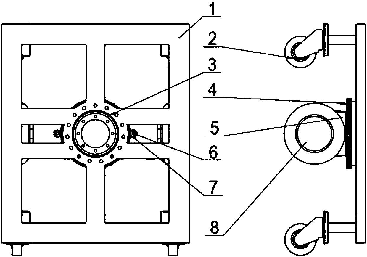
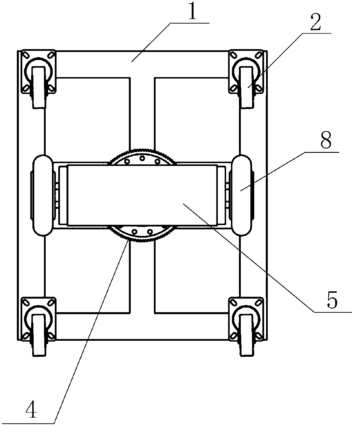
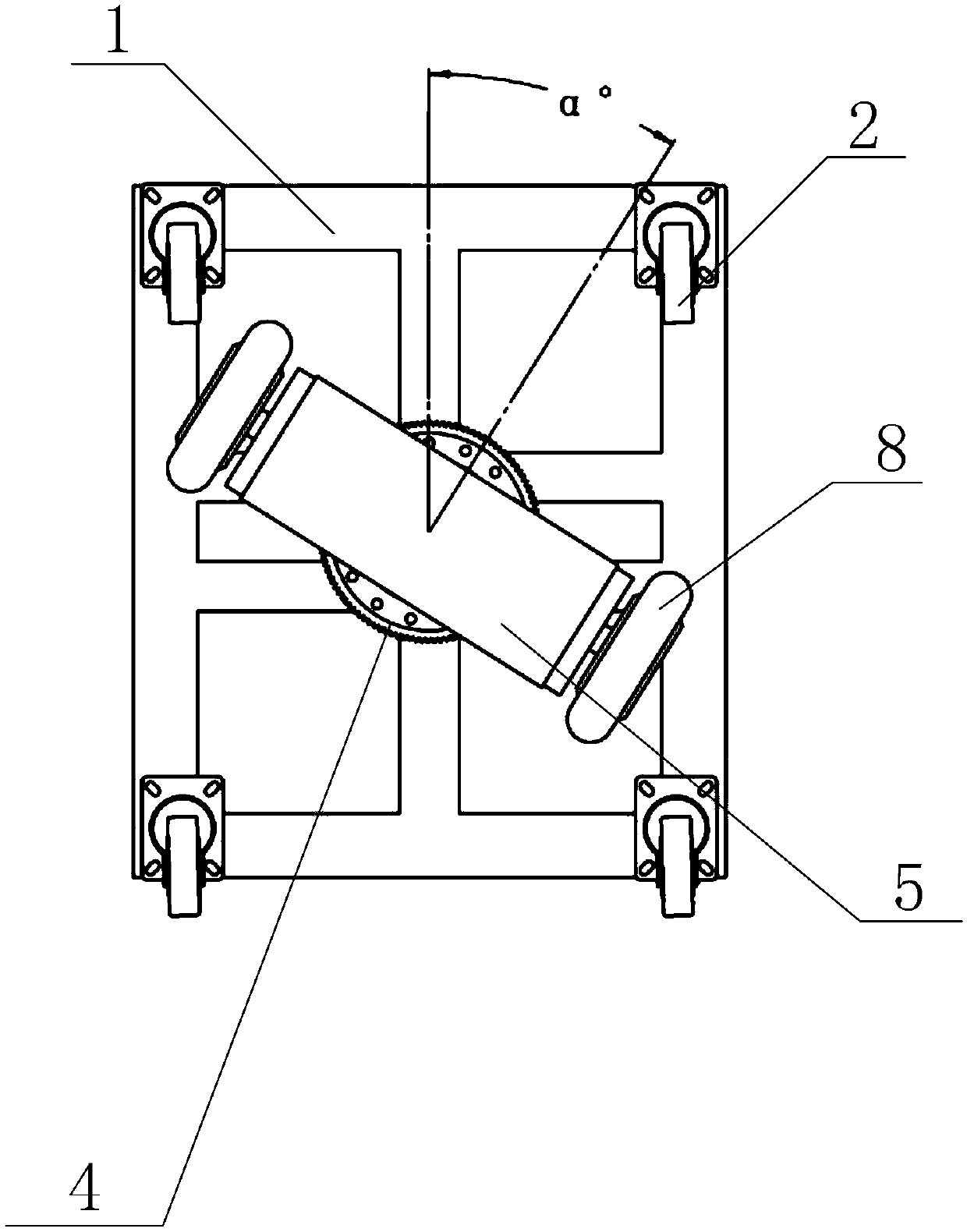
The invention discloses a walking chassis mechanism. When a rotary motor is braked, forward or backward walking of the chassis mechanism is realized by respectively controlling two driving wheels to run at the same speed and in the same direction; when the rotary motor is braked, the turning of the chassis mechanism is realized by controlling the two driving wheels run at differential speeds and in the same direction; when the rotary motor is braked, in-situ rotation of the chassis mechanism is realized by controlling the two driving wheels to run at the same speed and in opposite directions;and when the rotary motor is in a driving state, the two driving wheels are controlled to run at the same speed and in the opposite directions, so that the forward direction of a driving wheel frame and the forward direction of a chassis form a certain deflection angle, and then the two driving wheels are forced to run at the same speed and in the same direction to achieve the purpose of translating in any direction. The front-back walking and the front-back turning walking of the walking chassis mechanism can be realized, and the translation in any direction and the in-situ rotation can alsobe realized. The invention also provides a robot with the walking chassis mechanism.

Description

technical field [0001] The invention relates to the field of robots, in particular to a walking chassis mechanism and a robot. Background technique [0002] At present, many production enterprises at home and abroad still rely on manual production of production materials and workpieces, which cannot meet the needs of fully automated production. The increase in labor costs and labor intensity has restricted the development of enterprises. Many enterprises are trying to reduce labor costs. There are not many people who really find a better method. They can only rely on manual turnover of workpieces between stations, and the number of labor cannot be reduced. The labor cost is high, the production quality is unstable, the production cost is high, and it is impossible to meet the requirements of mass production. , because the production speed cannot be increased, and there are potential safety hazards in the equipment, which seriously affects the production operation. [0003] ...

Claims


Application Information

Patent Timeline
IPC IPC(8): B25J5/00B25J9/00
CPCB25J5/007B25J9/0009
Inventor 王宏玉徐方徐峰边弘晔李学威栾显晔
Owner SHENYANG SIASUN ROBOT & AUTOMATION
Why Eureka
Try Eureka