
A Capacitorless Low Dropout Linear Regulator

A low-dropout linear, capacitor-free technology, applied in the direction of instruments, electric variable adjustment, control/regulation systems, etc., can solve the problems affecting the performance of the circuit system, the deterioration of the power supply rejection ratio, and the deterioration of transient characteristics, etc., to achieve improved Effects of system efficiency, size reduction, and bandwidth expansion

Active Publication Date: 2020-07-31
UNIV OF ELECTRONICS SCI & TECH OF CHINA
View PDF7 Cites 0 Cited by
  • Summary
  • Abstract
  • Description
  • Claims
  • Application Information

AI Technical Summary

Problems solved by technology

However, traditional LDOs without output capacitors are faced with multiple pressures of poor stability, PSRR and transient characteristics, which seriously affect the performance of the circuit system.

Method used


Image

  • A Capacitorless Low Dropout Linear Regulator
  • A Capacitorless Low Dropout Linear Regulator
  • A Capacitorless Low Dropout Linear Regulator

Examples


Embodiment Construction

[0040] The technical solutions of the present invention will be described in detail below with reference to the accompanying drawings and specific embodiments.

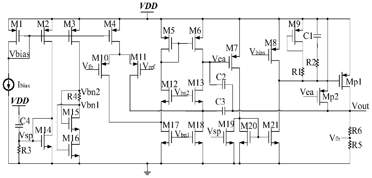
[0041] A capacitorless low-dropout linear regulator proposed by the present invention includes a bias circuit, an operational amplifier circuit, a compensation circuit, a power tube and a feedback loop, wherein the bias circuit is used to provide a first bias voltage V bn1 , the second bias voltage V bn2 , the third bias voltage Vsp and the first bias current; such as figure 1 An implementation form of the bias circuit is shown, including the eighth PMOS transistor M1, the ninth PMOS transistor M2, the tenth PMOS transistor M3, the eleventh PMOS transistor M4, the ninth NMOS transistor M15, and the tenth NMOS transistor M16 and the fourth resistor R4, the gate and drain of the eighth PMOS transistor M1 are short-circuited and connected to the bias current source Ibias with a fixed current value, and its gate outputs ...


PUM


Abstract

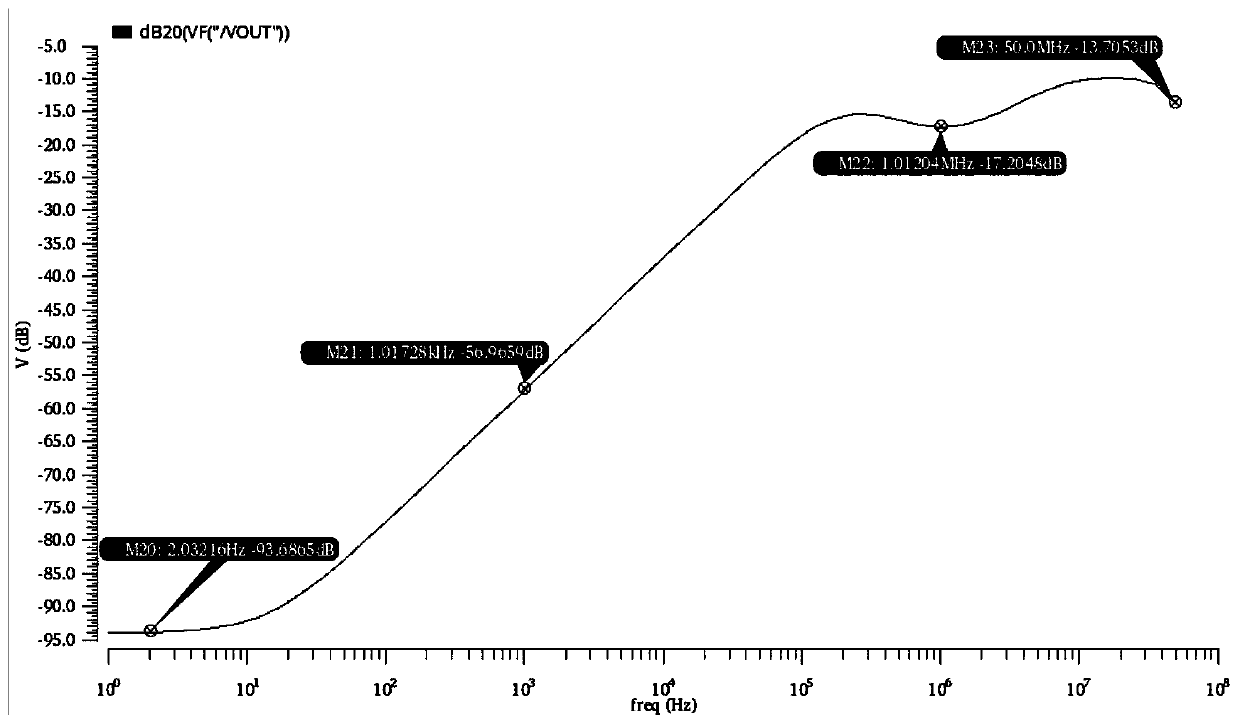
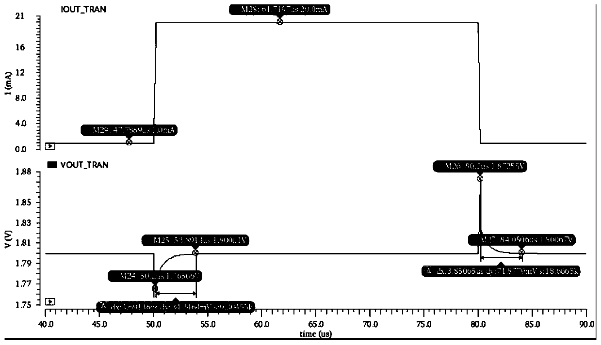
The utility model relates to a non-capacitance type low-dropout linear voltage stabilizer, which belongs to the technical field of electronic circuits. Including bias circuit, operational amplifier circuit, power supply voltage sampling circuit, compensation circuit, power tube and feedback loop, the bias circuit is used to provide bias, the operational amplifier circuit processes the feedback voltage and reference voltage, and transmits the processing results For the power tube and the feedback loop, the power supply voltage sampling circuit adopts the intermediate frequency PSRR improvement technology, and the change of the power supply voltage is sampled through the fourth capacitor, so that the gate voltage of the first power tube can offset the change of the power supply voltage, and the intermediate frequency PSRR is improved; the compensation circuit passes The second capacitor makes the output directly coupled to the gate of the third PMOS tube, which has a transient enhancement effect, and at the same time, the third capacitor cuts off the feedforward path, expands the bandwidth, and improves the influence of the second capacitor; the power tube adopts auxiliary power tube and main power The method of separate control of the tubes improves the system efficiency at light loads, and at the same time reduces the gate parasitic capacitance of the main power tubes to improve system stability.

Description

technical field [0001] The invention relates to electronic circuit technology, in particular to a Capless low-dropout linear voltage regulator circuit. Background technique [0002] Linear regulators (LDOs) are widely used in electronic products due to their low operating voltage, low output noise, small size and simple application. Traditional LDOs all need external capacitors at the output to ensure that the LDO works normally in the circuit system. With the development of system-on-chip (SOC), it is required to reduce peripheral circuits as much as possible, and more and more modules are incorporated into the chip. For the SOC, if the LDO in the system integrates the capacitor on-chip, the chip area will be greatly increased; if the off-chip capacitor is used, the pins of the chip need to be increased. Therefore, in terms of the application cost of SOC and the reliability of LDO itself, designing a Capless LDO circuit has become a hot technology in LDO design today. Ho...

Claims


Application Information

Patent Timeline
Patent Type & Authority Patents(China)
IPC IPC(8): G05F1/46
CPCG05F1/461
Inventor 李泽宏胡任任杨耀杰洪至超仪梦帅杨尚翰
Owner UNIV OF ELECTRONICS SCI & TECH OF CHINA
Learn More