Millimeter wave antenna system, metal shell, user terminal and millimeter wave communication equipment

A technology of millimeter-wave antennas and metal casings, applied in antennas, antenna arrays, antenna components, etc., can solve problems affecting terminal competitiveness

Active Publication Date: 2019-07-05
SHANGHAI AMPHENOL AIRWAVE COMM ELECTRONICS CO LTD
View PDF5 Cites 17 Cited by
  • Summary
  • Abstract
  • Description
  • Claims
  • Application Information

AI Technical Summary

Problems solved by technology

In the design of traditional terminals, space is precious, which directly affects the competitiveness of terminals

Method used


Image

  • Millimeter wave antenna system, metal shell, user terminal and millimeter wave communication equipment
  • Millimeter wave antenna system, metal shell, user terminal and millimeter wave communication equipment
  • Millimeter wave antenna system, metal shell, user terminal and millimeter wave communication equipment

Examples


Embodiment 1

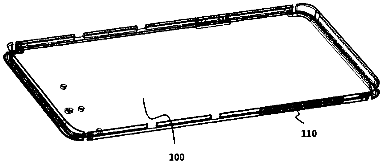
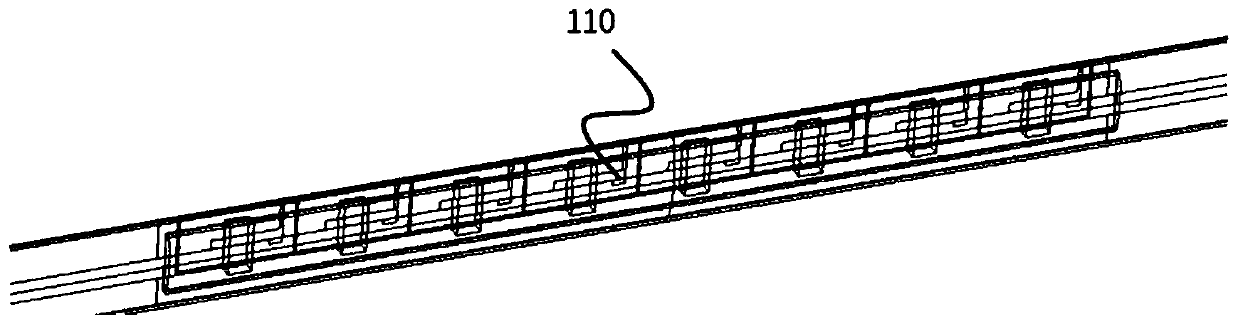
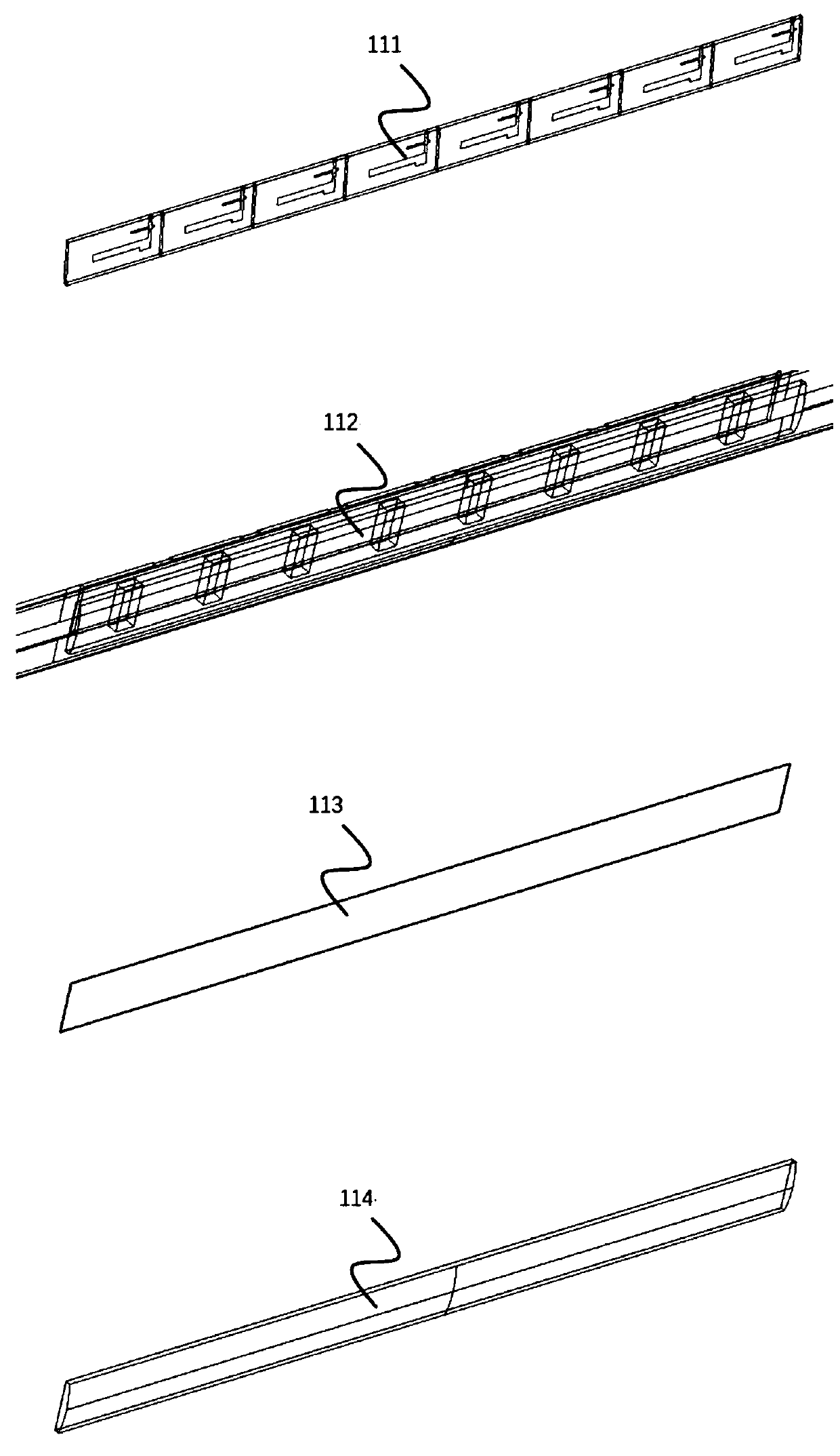
[0127] see figure 1 , figure 2 , image 3 , Figure 4 as well as Figure 5 , a millimeter-wave antenna system, comprising: a metal frame (shell) body 100 with an antenna slot 112; a high dielectric covering layer 114, located outside the antenna slot 112; a signal transmission unit 111, located on the side of the antenna slot 112 Inside; the signal transceiver assembly 115 electrically connected to the signal transmission unit 111; and the intermediate frequency and baseband processing unit 116 electrically connected to the signal transceiver assembly 115; wherein, the high dielectric covering layer 114, the antenna slot 112 and the signal transmission unit 111 These together constitute the dielectric resonant antenna array 110 of the millimeter wave antenna system.

[0128] In the above millimeter wave antenna system, the dielectric resonant antenna array 110 is arranged on the exterior surface of the communication terminal, and the dielectric resonant antenna array 110 ...

Embodiment 2

[0149] see Figure 15a to Figure 18 , based on the same inventive concept, the present invention also provides another millimeter-wave antenna system, including: at least one side is provided with antenna radiation slots (the first antenna radiation slot 101, the second antenna radiation slot 102, the third antenna radiation slot 103) metal frame (shell) body 100; high dielectric coating (the first high dielectric coating 200, the second high dielectric coating 210, the third high dielectric coating 220), located in the antenna radiation slot The outside of the phased array module (the first phased array module 300, the second phased array module 310, the third phased array module 320), located on the inside of the antenna radiation slot, and the phased array module The group is electrically connected to the radiation slot of the antenna; the high dielectric covering layer and the radiation slot of the antenna together form a radiator, and the phased array module forms a radia...

Embodiment 3

[0179] Based on the same inventive concept, the present invention also provides a phased array module, the phased array module can be arranged inside the antenna radiation slot of the metal frame (shell) body 100, and the outside of the antenna radiation slot is provided with The high-dielectric covering layer, the high-dielectric covering layer and the antenna radiation slot together form a radiator, and the phased array module forms a radiation exciter. The phased array module includes: a substrate 302, a phased array radiation slot, at least one transceiver chip, a mixer chip 303c electrically connected to the transceiver chip, and a connector 304; wherein, the side of the substrate 302 close to the antenna radiation slot is connected to the The inside of the antenna radiation slot is electrically connected; the phased array radiation slot is set on the side of the substrate 302 close to the antenna radiation slot; The total number of radio frequency channels of the chip is...


PUM


Abstract

The invention discloses a millimeter wave antenna system, which comprises a metal frame with an antenna gap, a high-dielectric coverage layer, a signal transmission unit, a signal receiving and sending component and an intermediate frequency and base band processing unit, wherein the high-dielectric coverage layer is arranged on the outer side of the antenna gap; the signal transmission unit is arranged on the inner side of the antenna gap; the signal receiving and sending component is electrically connected with the signal transmission unit; the intermediate frequency and base band processingunit is electrically connected with the signal receiving and sending component; and the high-dielectric coverage layer, the antenna gap and the signal transmission unit jointly form the dielectric resonant antenna array of the millimeter wave antenna system. The antenna system provided by the invention has the characteristics of small land occupation, more correctable factors, high working efficiency and the like. The invention also provides another millimeter wave antenna system, a phased array module, a metal shell, a method for eliminating the backward radiation of the antenna radiation gap of the metal shell, a user terminal and millimeter wave communication equipment.

Description

technical field [0001] The invention belongs to the design field of communication components, and in particular relates to a millimeter-wave antenna system, a phased array module, a metal shell, a method for eliminating the backward radiation of the antenna radiation gap of the metal shell, a user terminal, and millimeter-wave communication equipment . Background technique [0002] With the advent of the fifth generation of mobile communications (5G), millimeter wave array antenna technology has received more and more attention as one of its core technologies, and it will inevitably be applied to various terminals (such as mobile phones, tablet computers, readers, etc.) in the future. ). In the design of traditional terminals, space is precious, which directly affects the competitiveness of terminals. For example, a thin and delicate mobile phone is often more popular with consumers than a thicker mobile phone. For 5G millimeter-wave antenna arrays, factors such as the vo...

Claims


Application Information

Patent Timeline
Patent Type & Authority Applications(China)
IPC IPC(8): H01Q1/22H01Q1/24H01Q1/36H01Q1/50H01Q21/00
CPCH01Q1/22H01Q1/2258H01Q1/242H01Q1/36H01Q1/50H01Q21/00H01Q21/0006Y02D30/70
Inventor 胡沥王君翊蒋海英姜来新
Owner SHANGHAI AMPHENOL AIRWAVE COMM ELECTRONICS CO LTD
Why Eureka
Try Eureka