Check patentability & draft patents in minutes with Patsnap Eureka AI!

Resolver stator

A resolver and stator technology, which is applied in the direction of converting sensor output, instruments, measuring devices, etc., can solve the problem of easily damaged connecting wires, and achieve the effect of preventing easy damage

Active Publication Date: 2019-07-05
JAPAN AVIATION ELECTRONICS IND LTD
View PDF13 Cites 0 Cited by
  • Summary
  • Abstract
  • Description
  • Claims
  • Application Information

AI Technical Summary

Problems solved by technology

[0004] However, in the structure disclosed in Japanese Unexamined Patent Application Publication No. 2000-102203, when the operator holds the stator having the stator core 102, the operator may touch the hook hooked to the hook-shaped protrusion 101. cables, which may be easily damaged

Method used


Image

  • Resolver stator
  • Resolver stator
  • Resolver stator

Examples


no. 1 approach

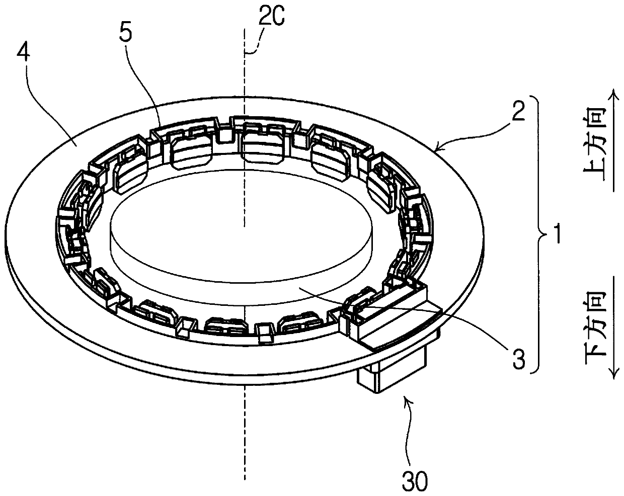
[0019] Refer to the following Figure 1 to Figure 6 The first embodiment will be described. like figure 1 As shown, a resolver 1 includes a resolver stator 2 and a resolver rotor 3 fixed to the shaft of, for example, an electric motor or an internal combustion engine (not shown). The resolver 1 is used to measure the angle and rotational speed of the above-mentioned shaft. The resolver 1 is a so-called inner rotor type, which has a structure in which a resolver rotor 3 is disposed radially inside with respect to a resolver stator 2 . The resolver stator 2 has a rotation shaft 2C.

[0020] In the following, as a general rule, the term “radial” refers to the radial direction of the resolver stator 2 and the term “circumferential” refers to the circumferential direction of the resolver stator 2 . The resolver stator 2 has an upward direction (first axial direction) parallel to the rotational axis 2C and a downward direction (second axial direction) opposite to the upward dir...

no. 2 approach

[0047] Next, refer to Figure 7 A second embodiment will be described. Differences between the second embodiment and the first embodiment are mainly described below, and redundant explanations are omitted.

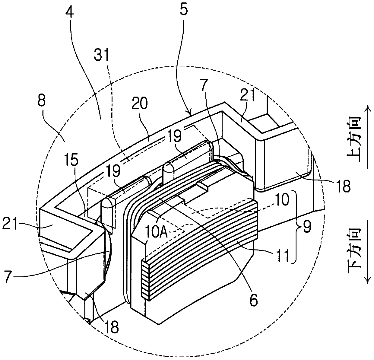
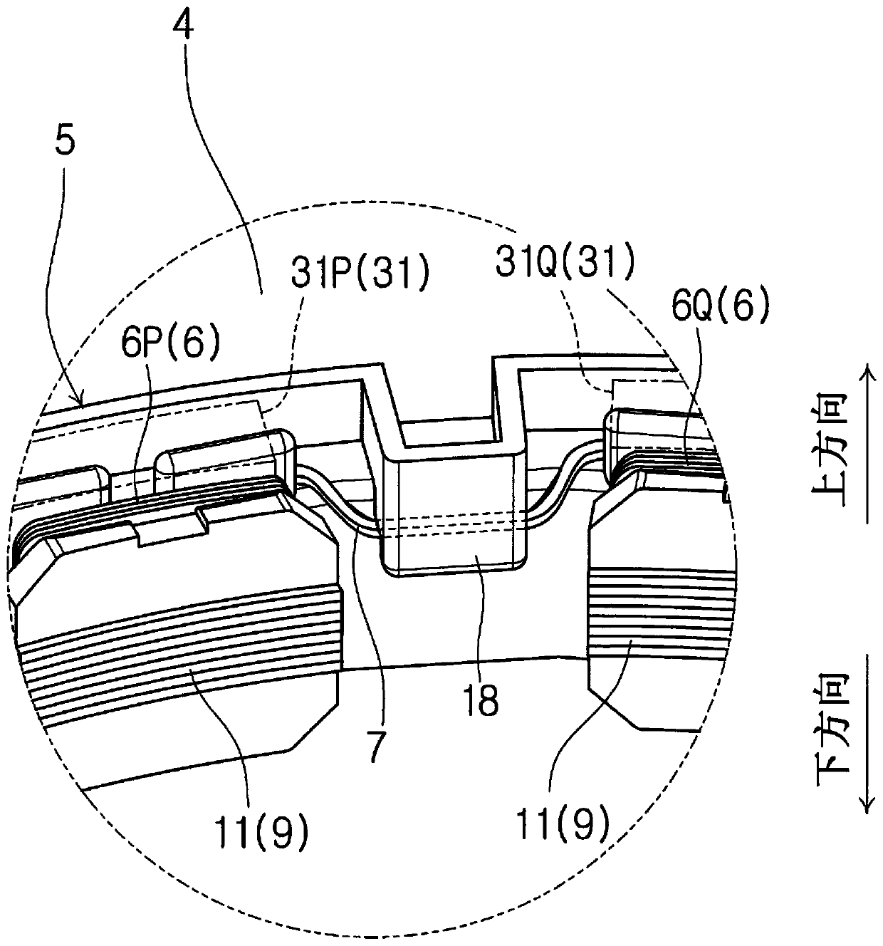
[0048] In the second embodiment, the facing surface 21A of each side facing wall portion 21 that faces the guide pin 19 is inclined so as to approach the guide pin 19 as it goes downward. According to the above structure, the space 50 surrounded by the two guide pins 19, the outer facing wall portions 20 and the two side facing wall portions 21 (see also Figure 5 ) is reduced in volume. Therefore, when the connecting wire 7 hooked to the guide pin 19 is fixed by an adhesive or the like, the amount of adhesive required is reduced, thereby contributing to weight reduction of the resolver stator 2 . noticed in Figure 7 In , the cross-sectional shape of the side facing wall portion 21 is illustrated by hatching.

[0049] Similarly, the facing surface 20A of the outer fa...


PUM


Abstract

A resolver stator (2) comprises: multiple coils (6) that are wound around multiple teeth (9); connecting lines (7) electrically connecting the multiple coils (6) with each other; and a guide hook (18)which guides the connecting line (7). Each connecting line (7) at least partially extends from a first coil outside space (31P) that is at an outer side of a first coil (6P) in the radial direction and an upper side of a stator core (4), to a second coil outside space (31Q) that is at an outer side of a second coil (6Q) in the radial direction and the upper side of the stator core (4). From the first coil outside space (31P) to the second coil outside space (31Q), the connecting line (7) is hung on the guide hook (18), thereby being curved to be projected downwards. The guide hook (18) protrudes inwards and downwards in the radial direction and opposes the connecting line (7) in a radial direction.

Description

[0001] This application is a divisional application, and its original application is a Chinese invention patent application with the application number 201710033431.1, the application date is January 18, 2017, and the invention name is "resolver stator". technical field [0002] The invention relates to a resolver stator. Background technique [0003] as in this application Figure 8 As shown, Japanese Unexamined Patent Application Publication No. 2000-102203 discloses a stator core 102 provided with a hook-shaped protrusion 101 for hooking two The connection line between the teeth 100 . [0004] However, in the structure disclosed in Japanese Unexamined Patent Application Publication No. 2000-102203, when the operator holds the stator having the stator core 102, the operator may touch the hook hooked to the hook-shaped protrusion 101. cables, which may be easily damaged. [0005] The object of the present invention is to provide a stator which prevents the connecting wire...

Claims


Application Information

Patent Timeline
Patent Type & Authority Applications(China)
IPC IPC(8): H02K24/00H02K3/52G01D5/20
CPCG01D5/2066H02K3/522H02K24/00H02K2203/06
Inventor 尾崎仁亮
Owner JAPAN AVIATION ELECTRONICS IND LTD
Features
  • R&D
  • Intellectual Property
  • Life Sciences
  • Materials
  • Tech Scout
  • Unparalleled Data Quality
  • Higher Quality Content
  • 60% Fewer Hallucinations
Learn More