Autonomous travel-type cleaner

A technology of vacuum cleaners and suction parts, which is applied in the installation of suction nozzles and electrical equipment, etc., can solve the problems of residue and insufficient inhalation of garbage.

Active Publication Date: 2019-07-05
PANASONIC INTELLECTUAL PROPERTY MANAGEMENT CO LTD
View PDF6 Cites 5 Cited by
  • Summary
  • Abstract
  • Description
  • Claims
  • Application Information

AI Technical Summary

Problems solved by technology

Therefore, the suction of the garbage on the wall/corner become...

Method used


Image

  • Autonomous travel-type cleaner
  • Autonomous travel-type cleaner
  • Autonomous travel-type cleaner

Examples


Embodiment approach

[0036] Below, refer to Figure 1 to Figure 13 The schematic structure of the self-propelled (vacuum) cleaner in the embodiment of the present invention will be described.

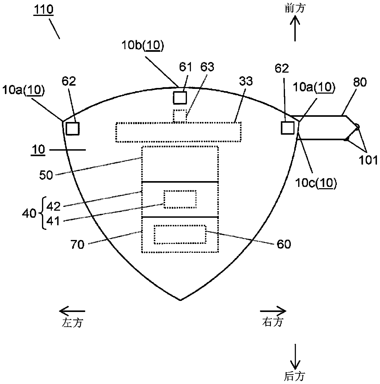
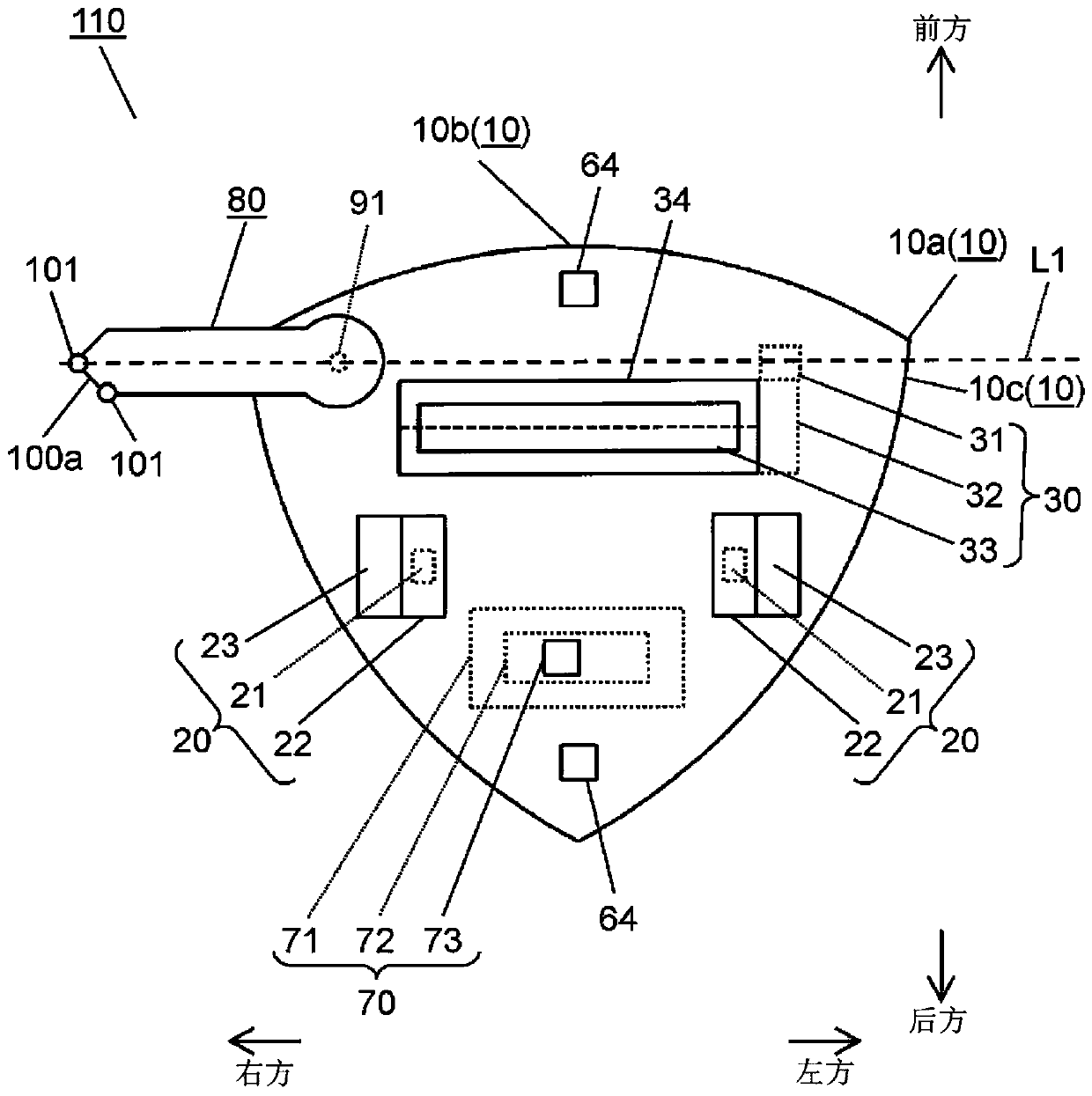
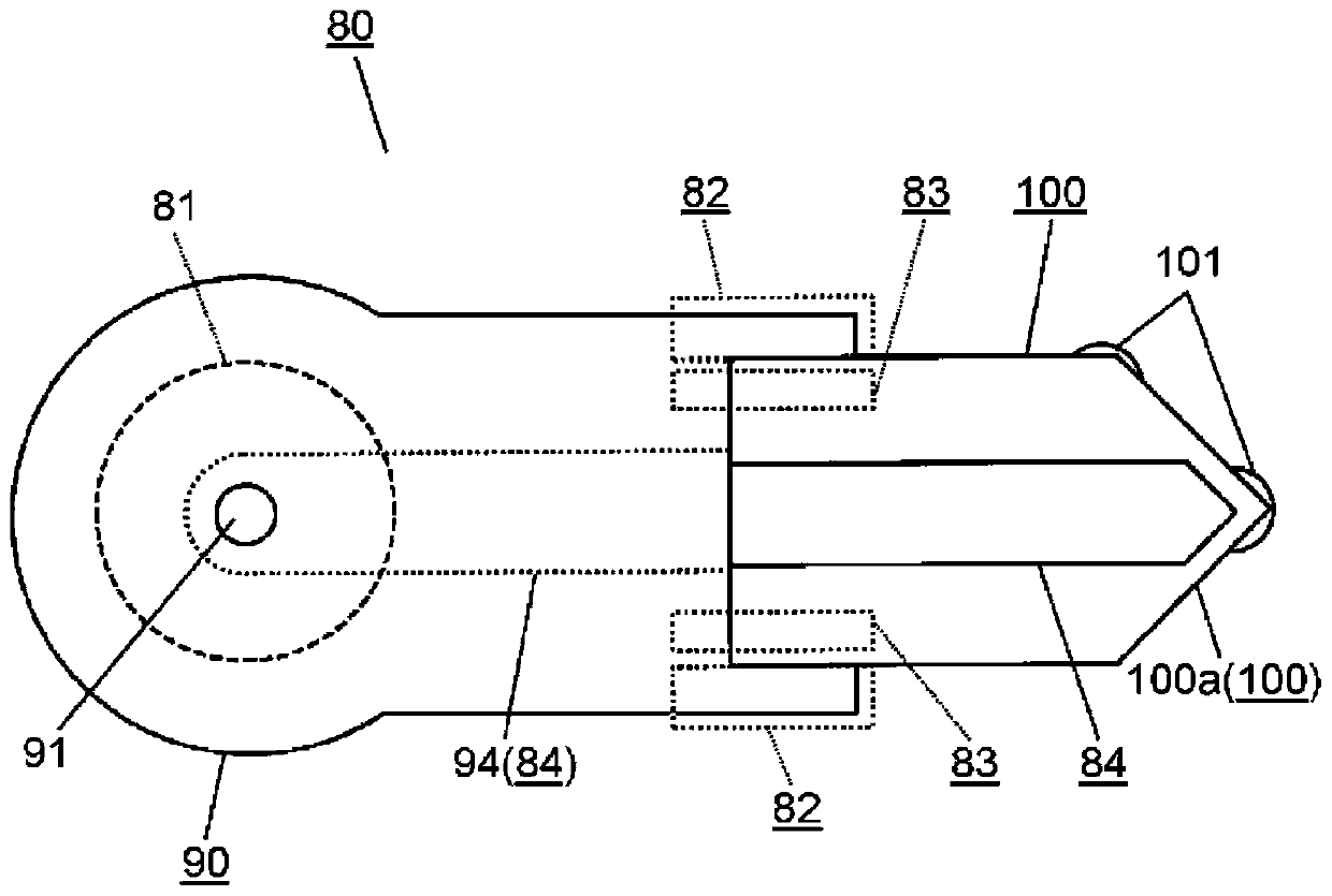
[0037] figure 1 It is a top view of the self-propelled vacuum cleaner in embodiment of this invention. figure 2 It is a bottom view of the self-propelled vacuum cleaner. image 3 It is a bottom view of the side suction part unit of this self-propelled cleaner. Figure 4 It is the bottom view of the side suction part rear part of this side suction part unit. Figure 5 It is a plan view of the side suction part front part of this side suction part unit. Image 6 is a bottom view of the front part of the side attraction, Figure 7 It is a block diagram showing the function of the electrical system of this self-propelled vacuum cleaner.

[0038] In addition, the self-propelled vacuum cleaner 110 of the present embodiment is exemplified by a robot-type vacuum cleaner that autonomously travels on the clea...


PUM


Abstract

The present invention is provided with: a body (10) having built therein a suction unit for suctioning garbage; and a side suction part unit (80) that is rotatably provided on the body (10) via a rotating shaft (91), and that cleans walls and corners by suction. The side suction part unit (80) has a tip part (100a) having a triangular shape the tip of which protrudes, a guide member (101) providedon the tip part (100a), a suction air path that communicates with the suction unit, and a longitudinal extension mechanism. Accordingly, the longitudinal extension mechanism moves the tip part (100a)of the side suction part unit (80) along a wall. In addition, the guide member (101) reduces obstruction of the travel of the body (10). As a result, garbage on walls and in corners can be suctionedwith greater certainty.

Description

technical field [0001] The invention relates to an autonomous walking vacuum cleaner. Background technique [0002] Conventional self-propelled vacuum cleaners include a main body on which various components are mounted, a drive device for moving the main body, a main brush, a suction device, and the like. The main brush is arranged at the suction port formed in the main body, and collects the garbage present on the cleaning surface. The suction device sucks garbage from the suction port of the main body. [0003] Below, use Figure 14 A conventional self-propelled vacuum cleaner will be described. [0004] Figure 14 It is a plan view showing the operation of a conventional self-propelled vacuum cleaner. [0005] like Figure 14 As shown, the main body of the conventional self-propelled vacuum cleaner 200 has a substantially circular shape. Utilizes a round body to achieve high maneuverability. [0006] like Figure 14 As shown, in general, a room that is an area to be...

Claims


Application Information

Patent Timeline
IPC IPC(8): A47L9/28A47L9/02
CPCA47L9/02A47L9/28
Inventor 渡边优冈山雅人中西邦行
Owner PANASONIC INTELLECTUAL PROPERTY MANAGEMENT CO LTD
Why Eureka
Try Eureka