Cloth-cutting apparatus of sewing machine

A sewing machine and cloth cutting technology, which is applied to sewing machine components, sewing equipment, textiles and papermaking, etc., can solve problems such as inability to eliminate the inside of the device, serious sintering of the device, and poor mechanical action.

Inactive Publication Date: 2006-03-08
JUKI CORP
View PDF2 Cites 1 Cited by
  • Summary
  • Abstract
  • Description
  • Claims
  • Application Information

AI Technical Summary

Problems solved by technology

[0007] However, in the techniques described in Patent Document 1 and Patent Document 2, even though most of the accumulated cloth waste can be discharged, the problem of fine cloth waste entering the interior of the device from the gap portion of the device cannot be eliminated.
Therefore, the cloth dust that entered the inside of the device caused mechanical failure, and forced oiling of the operating shaft and the like also caused cloth dust to enter between the operating shaft and the bushing, causing very serious problems such as device sintering.

Method used


Image

  • Cloth-cutting apparatus of sewing machine
  • Cloth-cutting apparatus of sewing machine
  • Cloth-cutting apparatus of sewing machine

Examples


Embodiment Construction

[0029] Embodiments of the cloth cutting device (hereinafter referred to as the cloth cutting device) of the sewing machine of the present invention will be described in detail below with reference to the accompanying drawings. In addition, in this embodiment, a right cutter device that cuts the cloth on the right side in the cloth feeding direction will be described as an example.

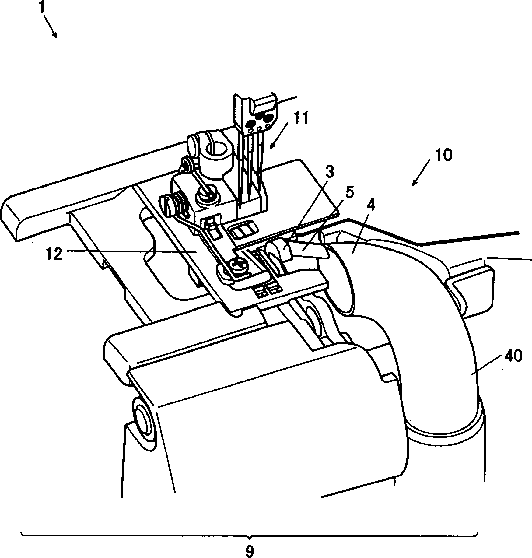
[0030] Such as figure 1 As shown, the cloth cutting device 1 is arranged near the needle plate 12 of the sewing machine frame 10, and the cloth cutting position is set at approximately the same height as the needle plate 12.

[0031] This cloth cutting device 1 has: a fixed knife unit 2 and a movable knife unit 3 for cutting cloth; The cloth waste guide part 5 of the suction part 4.

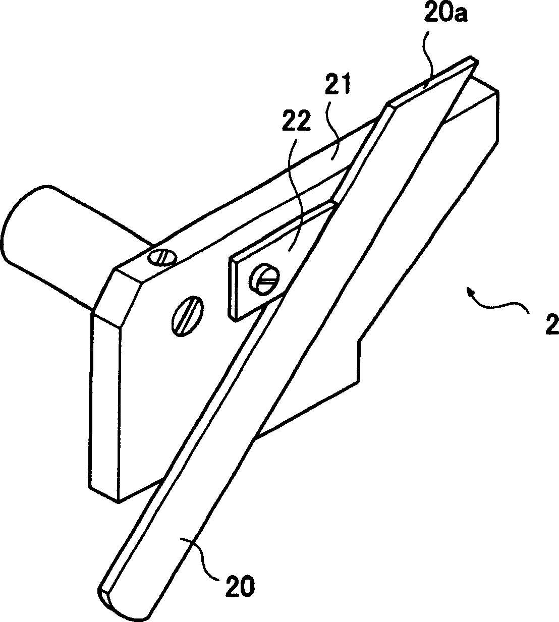
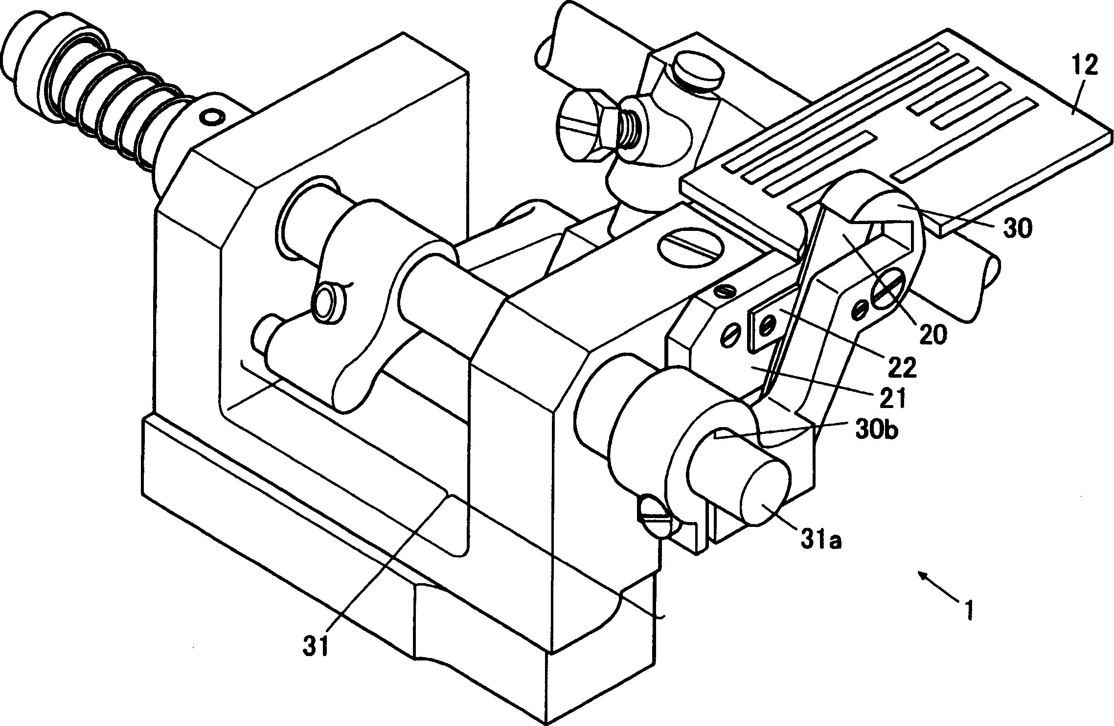
[0032] Fixed cutter part 2, such as figure 2 As shown, there are: an elongated fixed cutter 20 with a blade portion 20a at the upper end, a fixed cutter mounting seat 21 that is arranged on the sewing machine fram...


PUM


Abstract

A lint guide part 5 is provided in a clearance between a moving knife 30 and an opening part 40a. The end face of the lint guide part 5 opposed to the opening part 40a is formed into the same shape to that of the opening part 40a to efficiently exert a suction force. The lint guide part 5 is connected to the moving knife 30 and vertically move integrated therewith, and the opening part 40a and the end face of the lint guide part 5 are disposed on the same height at the lowermost end position to improve the lint collecting efficiency. To provide a cloth cutting knife device of a sewing machine causing neither malfunction due to the intrusion of lint produced when cutting a cloth by the cloth cutting knife device nor seizure of the sewing machine due to the lint absorbing oil.

Description

technical field [0001] The invention relates to a cloth cutting device of a sewing machine. Background technique [0002] Conventionally, there is known a cloth cutting device on a sewing machine in which a movable knife can be raised and lowered above a needle plate by swinging and rotating a movable knife shaft supporting the movable knife, and the cloth can be cut together with a fixed knife. [0003] The cloth cutting device is composed of a fixed knife mounting seat provided on the needle plate and fixed on the knife mounting seat, and is driven by a movable knife driving mechanism to swing and rotate. The blade part of the movable cutter slides in contact with each other, and cuts the cloth conveyed by the cloth feeding mechanism sequentially. [0004] At this time, at the position where the above-mentioned fixed knife and the movable knife cut the cloth, cloth waste is generated along with the cloth cutting. In order to prevent this cloth waste from accumulating ins...

Claims


Application Information

Patent Timeline
Patent Type & Authority Applications(China)
IPC IPC(8): D05B37/06D05B81/00
Inventor 小川达矢
Owner JUKI CORP
Why Eureka
Try Eureka