Drive Device for Fuel Injection Device, and Fuel Injection System

a fuel injection device and fuel injection technology, applied in the direction of machines/engines, electric control, instruments, etc., can solve the problems of increasing the minimum injection quantity and the difficulty of using the intermediate lift region from the viewpoint of stable combustion, and achieve the effect of reducing the controllable minimum injection quantity

Active Publication Date: 2016-06-23
HITACHI ASTEMO LTD
View PDF0 Cites 76 Cited by
  • Summary
  • Abstract
  • Description
  • Claims
  • Application Information

AI Technical Summary

Benefits of technology

[0016]According to the present invention, the valve opening start timing of a fuel injection device can be detected and therefore, individual variations of the injection quantity of the fuel injection device and variations between cylinders of the fuel injection start timing can be reduced and a fuel injection system constructed of the fuel injection device capable of reducing a controllable minimum injection quantity and a drive device can be provided.

Problems solved by technology

However, the time needed for a needle to reach a valve closed position after the injection pulse is stopped varies due to a rebound phenomenon (bound behavior of the needle) that occurs when the needle collides against a fixed core or a stopper that regulates a displacement of the needle in a region where the injection pulse width is short, posing a problem that the injection quantity does not change linearly with respect to the injection pulse width and thus, a controllable minimum injection quantity of the fuel injection device increases.
Also due to the rebound phenomenon of the needle, the injection quantity may not be stable from fuel injection device to fuel injection device and it is unavoidable to set an individual fuel injection device with the largest injection quantity as the controllable minimum injection quantity, leading to an increased minimum injection quantity.
Then, the required injection quantity is small in an intermediate lift region and the influence of individual variations of the injection quantity on injection quantity errors becomes pronounced, which makes it difficult to use the intermediate lift region from the viewpoint of stable combustion.

Method used


Image

  • Drive Device for Fuel Injection Device, and Fuel Injection System
  • Drive Device for Fuel Injection Device, and Fuel Injection System
  • Drive Device for Fuel Injection Device, and Fuel Injection System

Examples


example 1

[0065]Hereinafter, the operation of a fuel injection system including a fuel injection device and a drive device according to the present invention will be described using FIGS. 1 to 7.

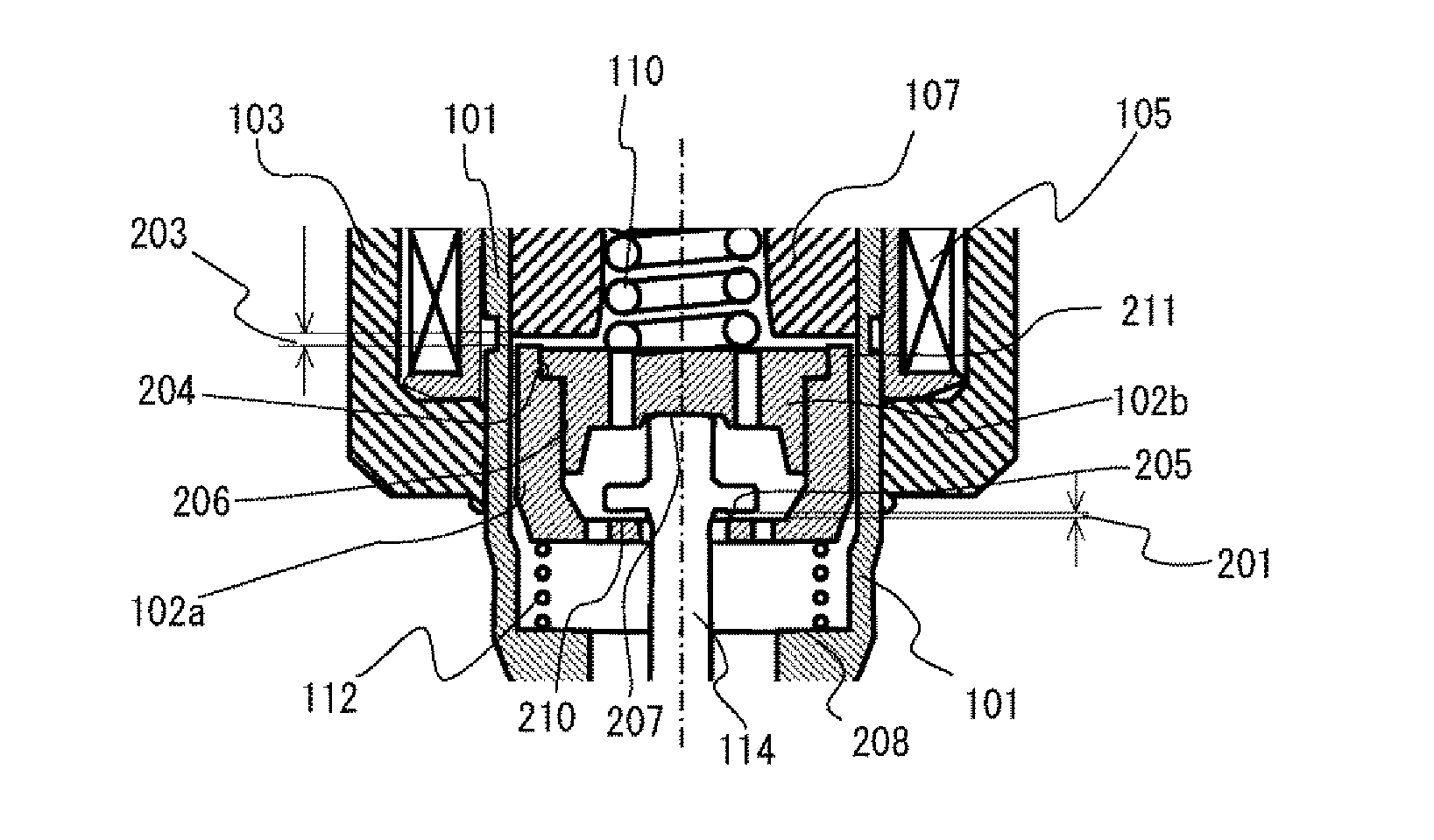
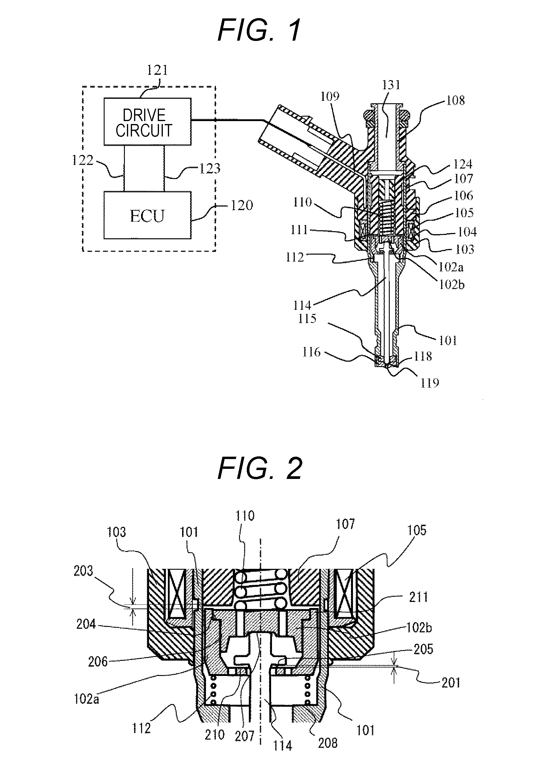
[0066]First, the configuration of the fuel injection device and the drive device and the basic operation thereof will be described using FIG. 1. FIG. 1 is a diagram showing a longitudinal view of a fuel injection device and an example of the configuration of a drive circuit 121 to drive the fuel injection device and an engine control unit (ECU) 120. The ECU 120 and the drive circuit 121 are configured as separate devices in the present example, but the ECU 120 and the drive circuit 121 may also be configured as an integrated device. A device constructed of the ECU 120 and the drive circuit 121 will be described as a drive device below.

[0067]The ECU 120 fetches signals showing the state of an engine from various sensors and calculates the injection pulsed width and injection timing to control the injec...

example 2

[0156]Using FIGS. 19, 20, 21, 22, 23, 24, 25, and 26, the configuration of the fuel injection device and the drive device in Example 2 of the present invention will be described. FIG. 19 is an enlarged view of a drive unit cross section in a valve closed state in which the valve body and the valve seat of the fuel injection device according to Example 2 of the present invention are in contact. FIG. 20 is a diagram enlarging a longitudinal section of a valve body tip portion of the fuel injection device. FIG. 21 is an enlarged view of the drive unit cross section when the valve body of the fuel injection device according to Example 2 is in a valve open state. FIG. 22 is an enlarged view of the drive unit cross section at the instant when the valve body comes into contact with a valve seat 118 after starting to close from a valve open state. FIG. 23 is a diagram showing the configuration of the drive device according to Example 2 of the present invention. FIG. 24 is a diagram showing ...

example 3

[0166]The control technique to correct the injection quantity of the fuel injection device 840 and the fuel injection device 2305 according to Examples 1 and 2 respectively according to Example 3 of the present invention will be described using FIGS. 27 to 30.

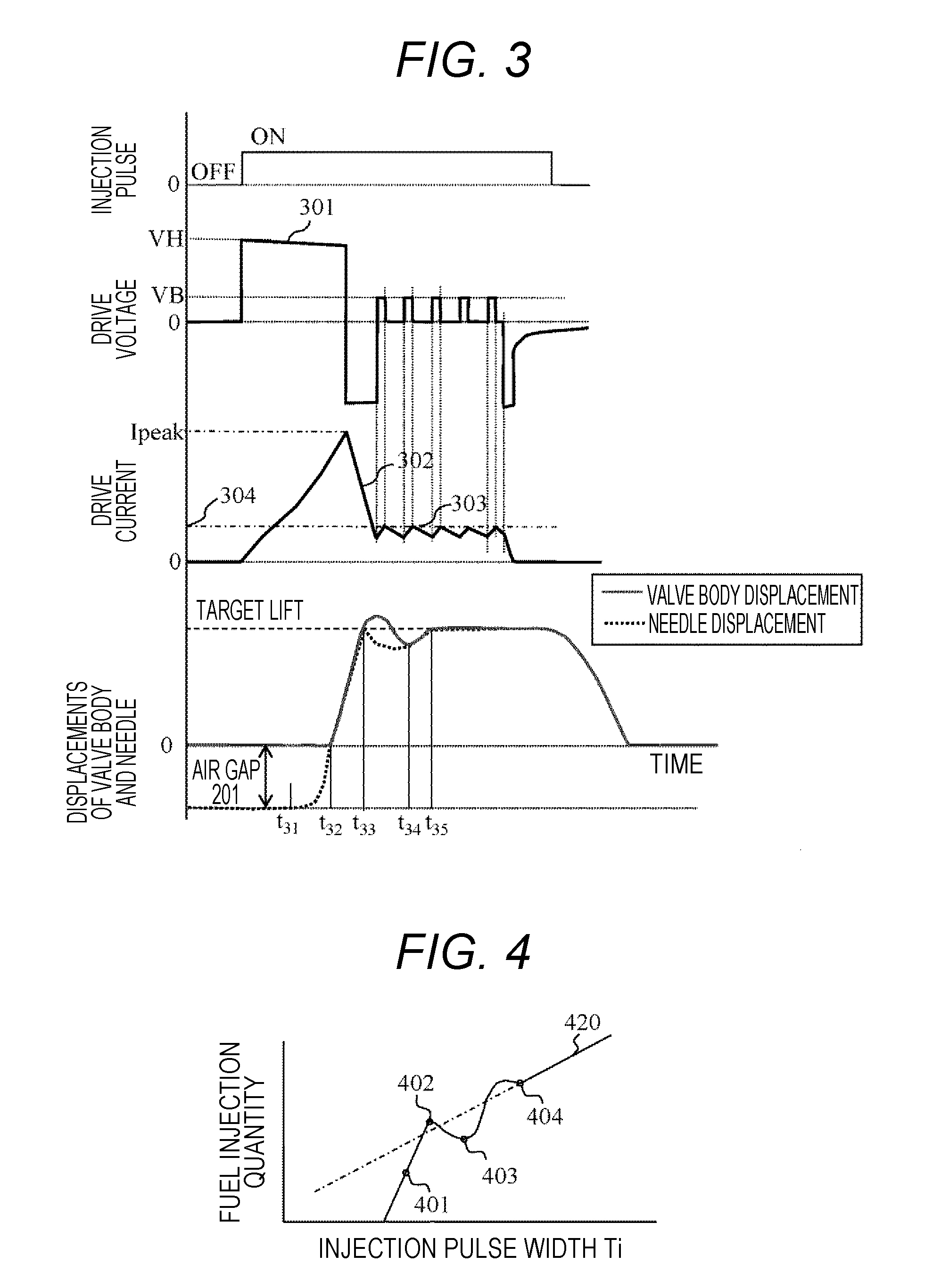
[0167]FIG. 27 is a diagram showing the relationship between the terminal voltage Vinj of the fuel injection device 840 or the fuel injection device 2305, the drive current, the magnetic suction force acting on the needle 102 or the second needle 1902, the valve body driving force acting on the valve body 114 or the second valve body 1907, the displacement of the valve body 114 or the second valve body 1907, and the displacement of the needle 102 or the second needle 1907 when used by, among cases in which the fuel injection device 840 or the fuel injection device 2305 is driven by a technique according to Example 3, holding the valve body 114 or the second valve body 1907 in a target lift position for a fixed time and the time....


PUM


Abstract

A drive device capable of detecting individual variations of an injection quantity of a fuel injection device of each cylinder and adjusting a current waveform provided to an injection pulse width and a solenoid such that the individual variations of the fuel injection devices are reduced. The fuel injection device in the present invention includes a valve body that closes a fuel passage by coming into contact with a valve seat and opens the fuel passage by separating from the valve seat and a magnetic circuit constructed of a solenoid, a fixed core, a nozzle holder, a housing, and a needle and when a current is supplied to the solenoid, a magnetic suction force acts on the needle and the needle has a function to open the valve body by colliding against the valve body after performing a free running operation and changes of acceleration of the needle due to collision of the needle against the valve body are detected by a current flowing through the solenoid.

Description

TECHNICAL FIELD[0001]The present invention relates to a drive device that drives a fuel injection device for an internal combustion engine or a fuel injection system.BACKGROUND ART[0002]In recent years, tightening of emission control of carbon dioxide and concern about depletion of fossil fuel demand improvements of fuel consumption (fuel consumption rate) of internal combustion engines. Thus, efforts to improve fuel consumption by reducing various losses of an internal combustion engine are under way. In general, when losses are reduced, the power output necessary for operation of an engine can be reduced so that the minimum power output of the internal combustion engine can be reduced. In such an internal combustion engine, it becomes necessary to control and supply up to a small amount of fuel corresponding to the minimum power output.[0003]Also in recent years, a downsizing engine which reduces the size thereof by reducing the displacement and also obtains power output by a supe...

Claims


Application Information

Patent Timeline
Patent Type & Authority Applications(United States)
IPC IPC(8): F02D41/20F02M65/00F02M51/06
CPCF02D41/20F02M51/0685F02M65/005F02M61/1833F02D2200/063F02D41/0085F02D2041/2055F02D2041/2058F02D2041/2003F02D2041/2037
Inventor KUSAKABE, RYOABE, MOTOYUKIHATANAKA, AYUMUAONO, TOSHIHIROHIROTSU, TEPPEISAKAMOTO, HIDEYUKITOYOHARA, MASAHIROMUKAIHARA, OSAMUFUKUDA, TAKAOYASUKAWA, YOSHIHITOMIYAMOTO, AKIYASU
Owner HITACHI ASTEMO LTD
Why Eureka
Try Eureka