Apparatus and method for controlled cleaving

a technology of apparatus and controlled cleaving, which is applied in the direction of electrical apparatus, manufacturing tools, adhesives, etc., can solve the problems of difficult separating or cutting extremely hard and/or brittle materials such as glass or diamond, and the general use of substrate precision separation for fine tools and assemblies, and the difficulty of saw operation to achieve the fabrication of small complex structures or precision workpieces. severe limitations

Inactive Publication Date: 2005-07-14
SILICON GENERAL CORPORATION
View PDF10 Cites 80 Cited by
  • Summary
  • Abstract
  • Description
  • Claims
  • Application Information

AI Technical Summary

Benefits of technology

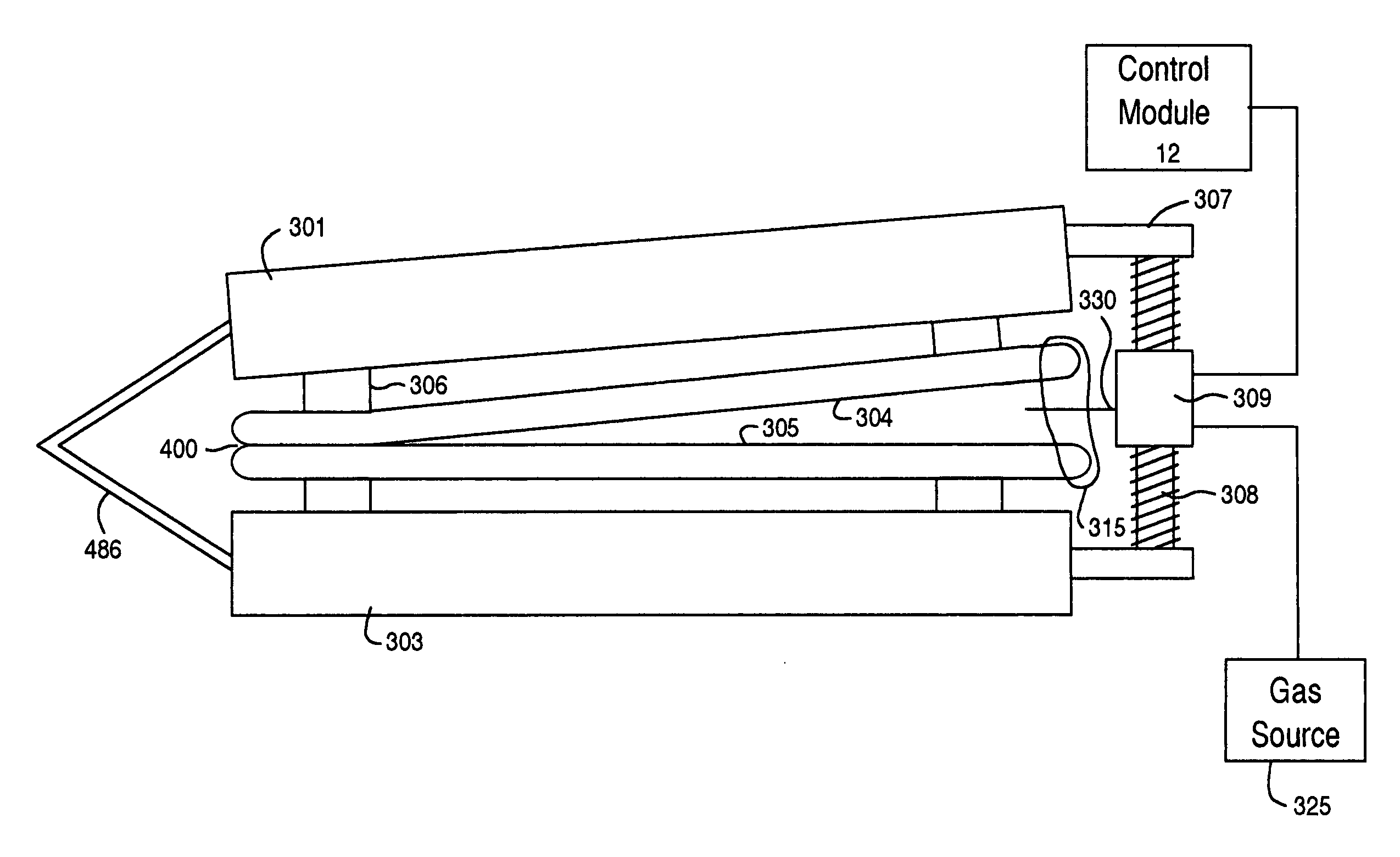
[0015] Embodiments of the present invention also include a method for initiating and cleaving a bonded substrate comprising of placing the bonded substrate on the bottom cleaving shell, then placing the top cleaving shell on the other side of the bonded substrate, the substrate comprising a first perimeter edge and a second perimeter edge, to compress and seal a compliant member against the first perimeter edge and the second perimeter edge of the substrate to form a selected volume, pressurizing the selected volume with a gas, wherein the gas is at a pressure capable of initiating a cleave front in the substrate, and providing a separating force substantially perpendicular to the cleave front. In addition, tensile forces are also applied from vacuum to the top and bottom shells to maintain separation of the cleave which prevents the substrate from touching after cleaving. In another embodiment of the invention, a blade edge is used to initiate propagation. In this embodiment of the invention, an electrically controlled motor coupled to a hinge mechanism controls the acceleration and velocity of the cleave front across the substrate.

Problems solved by technology

This technique, however, is often extremely rough and cannot generally be used for providing precision separations in the substrate for the manufacture of fine tools and assemblies.
Additionally, the saw operation often has difficulty separating or cutting extremely hard and / or brittle materials such as glass or diamond.
Although the techniques described above are satisfactory for the most part, as applied to cutting diamonds and glass material, they have severe limitations in the fabrication of small complex structures or precision work-pieces.
For instance, the above techniques are often “rough” and cannot be used with great precision in fabrication of small and delicate machine tools, electronic devices, or the like.
Additionally, the above techniques may be useful for separating one large plane of glass from another, but are often ineffective for splitting off, shaving, or stripping a thin film of material from a larger substrate.
Furthermore, the above techniques may often cause more than one cleave front, which join along slightly different planes, which is highly undesirable for precision cutting applications.
Other processing techniques such as using a release layer have had limited success.
Such release layer techniques often require wet chemical etching, which is often undesirable in many state of art applications.
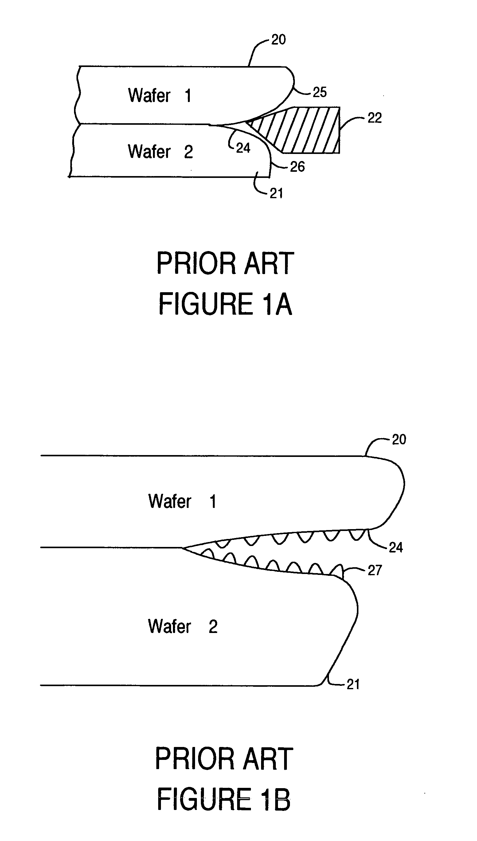
Although often satisfactory, using a blade for the initiating process can result in some deleterious conditions.
Under these conditions, surface damage can occur if the cleaved surfaces are allowed to contact each other after separation.
Many times, peaks 27 can be fractured, thus causing abrasion problems if the wafer surfaces come in contact again.
Abrasions on the surfaces have deleterious effects on subsequent processes such as scratching, thus resulting in poor quality of the finished good.

Method used


Image

  • Apparatus and method for controlled cleaving
  • Apparatus and method for controlled cleaving
  • Apparatus and method for controlled cleaving

Examples


Embodiment Construction

[0040] Reference will now be made in detail to the preferred embodiments of the invention, examples of which are illustrated in the accompanying drawings. While the invention will be described in conjunction with the preferred embodiments, it will be understood that they are not intended to limit the invention to these embodiments. On the contrary, the invention is intended to cover alternatives, modifications and equivalents, which may be included within the spirit and scope of the invention as defined by the appended claims. Furthermore, in the following detailed description of the present invention, numerous specific details are set forth in order to provide a thorough understanding of the present invention. However, it will be obvious to one of ordinary skill in the art that the present invention may be practiced without these specific details. In other instances, well-known methods, procedures, components, and circuits have not been described in detail as not to unnecessarily o...


PUM

PropertyMeasurementUnit
pressureaaaaaaaaaa
outer diameteraaaaaaaaaa

Abstract

An apparatus and method for controlled cleaving is presented. Embodiments of the present invention include an apparatus for cleaving a substrate comprising a bottom shell coupled to a hinge mechanism, a top shell coupled to the hinge mechanism, a plurality of o-rings or suction cups coupled to the top and bottom shells for providing a suction force sufficient to exert a tensile force to the top and bottom of a substrate, a compliant member for sealing a portion of a grove edge of a substrate and for maintaining a pressure inside a volume formed between the groove edge and the groove edge of the substrate, a gas port for supplying gas to the volume, and a height adjustment mechanism coupled to the top shell and the bottom shell for separating the top shell from the bottom shell. One embodiment of the invention eliminates the use of gas system and is replaced by a blade edge to initiate propagation and applied tensile force of suction cups to apply tensile forces prior to initiation, control cleave process and maintain layer separation during and after cleaving.

Description

BACKGROUND OF THE INVENTION [0001] 1. Field of the Invention [0002] The field of the invention relates to the manufacture of substrates. More specifically, embodiments of the present invention relate to an apparatus and method for controlled cleaving. [0003] 2. Related Art [0004] Crafts people have been building useful articles, tools or devices using less useful materials for numerous years. In some cases, articles are assembled by way of smaller elements or building blocks. Alternatively, less useful articles are separated into smaller pieces to improve their utility. Examples of these articles to be separated include substrate structures such as a glass plate, a diamond, a semiconductor substrate, and others. [0005] These substrate structures are often cleaved or separated using a variety of techniques. In some cases, the substrates can be cleaved using a saw operation. The saw operation generally relies on a rotating blade or tool, which cuts the substrate material to separate t...

Claims


Application Information

Patent Timeline
Patent Type & Authority Applications(United States)
IPC IPC(8): B28D5/00B32B1/00H01L21/00H01L21/762
CPCB28D5/00Y10T156/1928H01L21/76251H01L21/67092B32B1/00
Inventor HENLEY, FRANCOISTEOH, HONGBEEPALER, ANTHONYLAMM, ALBERTONG, PHILIP
Owner SILICON GENERAL CORPORATION
Why Eureka
Try Eureka