Method and apparatus for cleaning a turbofan gas turbine engine

a gas turbine engine and turbofan technology, which is applied in the direction of machines/engines, liquid fuel engines, machines/engines, etc., can solve the problems of large air consumption of gas turbine engines, increased exposure to air contaminants, and gas turbines installed in aircrafts without filters, so as to reduce the negative effects of aero engine performance, reduce fuel consumption, and reduce engine life

Inactive Publication Date: 2006-03-09
ECOSERVICES
View PDF8 Cites 78 Cited by
  • Summary
  • Abstract
  • Description
  • Claims
  • Application Information

AI Technical Summary

Benefits of technology

[0018] Thus, an object of the present invention is to provide a device and a method for removing the different types of fouling found on the fan and in the core engine compressor of turbofan e...

Problems solved by technology

Gas turbines engines consume large quantities of air.
However, there are particles with properties of sticking on to components in the compressor's gas path.
However, gas turbines installed in aircrafts are not equipped with filters because it would create a substantial fall in pressure and are thereby more exposed to air contaminants.
However, after a period of operation a coating of foreign particles builds up.
Compressor fouling results in a change in the properties of the boundary layer air stream of the components.
The deposits result in an increase of the component surface roughness.
As air flows over the component surface the increase of surface roughness results in a thickening of the boundary layer air stream.
The thickening of the boundary layer air stream has negative effects on the compressor aerodynamics.
Further, the thicker boundary layer and the stronger wake turbulence formed at the blade trailing edge result in a reduced compression pressure gain which in turn results in the engine operating at a reduced pressure ratio.
Anyone skilled in the art of heat engine working cycles understands that a reduced pressure ratio result in a lower thermodynamic efficiency of the engine.
The compressor fouling not only reduces the mass flow and pressure gain but also reduces the compressor isentropic efficiency.
Reduced compressor efficiency means that the compressor requires more power for compressing the same amount of air.
The reduced mass flow, pressure ratio and isentropic efficiency reduce the engine thrust capability.
Throttling for more power means the consumption of fuel increases and thereby increasing operating costs.
Compressor fouling also has a negative effect to the environment.
With the increase of fuel consumption follows an increase of emissions of green house gas such as carbon dioxide.
The loss in performance caused by compressor fouling also reduces the durability of the engine.
Controlling this temperature is a key issue in engin...

Method used


Image

  • Method and apparatus for cleaning a turbofan gas turbine engine
  • Method and apparatus for cleaning a turbofan gas turbine engine
  • Method and apparatus for cleaning a turbofan gas turbine engine

Examples


Embodiment Construction

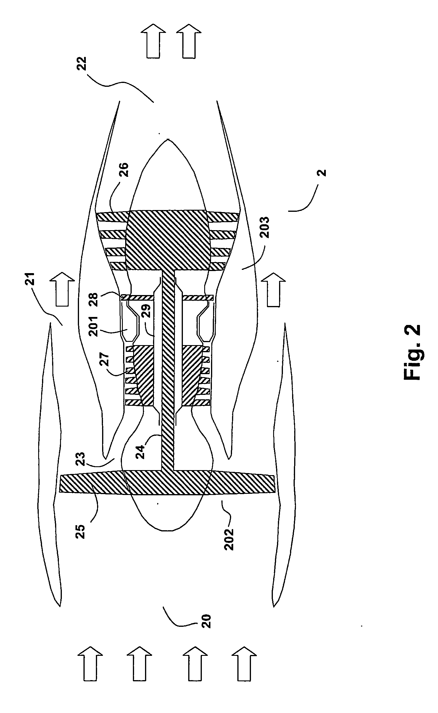
[0042] With reference now to FIG. 2, a two shaft unmixed turbofan aero engine will be described. The two shaft unmixed turbofan engine is one of several possible designs of a turbofan engine. This invention is not limited to the embodiment of this description and its figures as it is evident that the invention can be applied to other variants of turbofan engine designs such as the mixed turbofan engine or turbofan engines with one, three or more shafts. Characteristic for the turbofan engine on which the invention is suitable for practice is that the fan and its cone for splitting the airflow is rotating.

[0043] Engine 2 in FIG. 2 comprises of a fan unit 202 and a core engine unit 203. The engine is built around a rotor shaft 24 which at its front end is connected to a fan 25 and at the rear end turbine 26. Turbine 26 drives fan 25. A second shaft 29 is in form of a coaxial to first shaft 24. Shaft 29 is connected at its front end to compressor 27 and rear end to turbine 28. Turbine...


PUM


Abstract

Device for cleaning a gas turbine engine (2), and in particular an engine of turbofan type. The present invention further relates to a method for cleaning such a engine. The device comprises a plurality of nozzles (31, 33, 35) arranged to atomize cleaning liquid in the air stream in an air inlet (20) of the engine (2) up-stream of a fan (25) of the engine (2). According to the invention a first nozzle (31) is arranged at a position such that the cleaning liquid emanating from the first nozzle (31) impinges the surfaces of the blades (40) substantially on the pressure side (53); a second nozzle (35) is arranged at a position such that the cleaning liquid emanating from the second nozzle (35) impinges the surfaces of the blades (40) substantially on the suction side (54); and a third nozzle (33) is arranged at a position such that the cleaning liquid emanating from the third nozzle (33) passes substantially between the blades (40) and enters an inlet (23) of the core engine (203). Thereby, the different types of fouling found on the fan and in the core engine compressor of turbofan engine can be removed in an efficient manner.

Description

TECHNICAL FIELD [0001] The present invention generally relates to the field of cleaning gas turbine engines, and more specifically a method and apparatus for cleaning a turbofan gas turbine engine installed in an aircraft. BACKGROUND OF THE INVENTION [0002] A gas turbine installed as an aircraft engine comprises a compressor compressing ambient air, a combustor burning fuel together with the compressed air and a turbine for powering the compressor. The expanding combustion gases drive the turbine and also result in thrust used for propelling the air craft. [0003] Gas turbines engines consume large quantities of air. Air contains foreign particles in form of aerosols which enters the gas turbine compressor with the air stream. The majority of the foreign particles will follow the gas path and exit the engine with the exhaust gases. However, there are particles with properties of sticking on to components in the compressor's gas path. Stationary gas turbines like gas turbines used in ...

Claims


Application Information

Patent Timeline
IPC IPC(8): B08B5/04B08B9/00B08B9/027B08B9/04B08B3/00B05B1/02B08BB08B3/02B08B13/00F01D25/00F02C7/00F04D29/70
CPCB08B3/02F02K3/06F01D25/002B08B9/00F04D29/705B08B13/00F04D29/70F02C7/00
Inventor ASPLUND, PETERHJERPE, CARL-JOHAN
Owner ECOSERVICES
Why Eureka
Try Eureka