A high pressure separator

A high-pressure separator and tank technology, which is applied in the field of intelligent manufacturing, can solve the problems of reduced efficiency of liquid flowing into the separator, aggravated pipeline blockage, increased water surface fluctuations, etc., and achieves the effects of stable connection, increased buffering force, and calm water flow

Active Publication Date: 2021-08-06
山西盛达威科技有限公司
View PDF0 Cites 0 Cited by
  • Summary
  • Abstract
  • Description
  • Claims
  • Application Information

AI Technical Summary

Problems solved by technology

[0003] The working principle of the existing high-pressure separator is as follows: Figure 5 As mentioned above, the gas-liquid mixed fluid enters the separator through the gas-liquid inlet for basic phase separation, the gas enters the gas channel for gravity sedimentation to separate droplets, the liquid enters the liquid space to separate bubbles and solid impurities, and the gas is captured before leaving the separator. After the mist removes small droplets, it flows out from the air outlet, and the liquid flows out from the liquid outlet. When the liquid enters the separator again, the liquid will hit the baffle 11 instantly. When the traditional separator is in use, the baffle is hit by the liquid , a part of the liquid is backflowed by force, causing the impacted liquid to meet and mix with the newly injected liquid, resulting in a decrease in the efficiency of the liquid flowing into the separator, and during the reinjection of the liquid, the water flow will stir the liquid in the separator, resulting in The sediment in the separator is impacted and surged, and enters the pipeline with the water flow, causing the pipeline to be blocked. At the same time, after the baffle is used for a period of time, it is subjected to a strong impact, and the baffle falls off the separator, resulting in the buffering of the liquid being affected. Influenced by the increase of water surface fluctuations, further aggravating the clogging of pipelines, resulting in more water in the oil layer

Method used


Image

  • A high pressure separator
  • A high pressure separator
  • A high pressure separator

Examples


Embodiment Construction

[0018] Next, the technical solutions in the embodiments of the present invention will be apparent from the embodiment of the present invention, and it is clearly described, and it is understood that the described embodiments are merely embodiments of the present invention, not all of the embodiments. Based on the embodiments of the present invention, there are all other embodiments obtained without making creative labor without making creative labor premises.

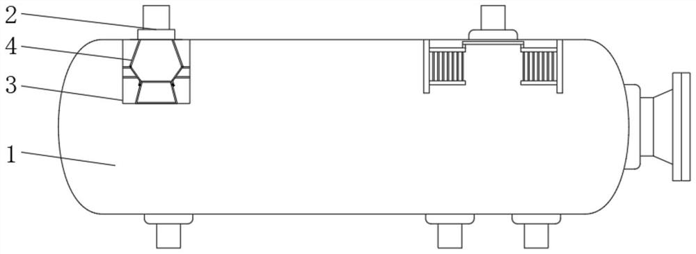
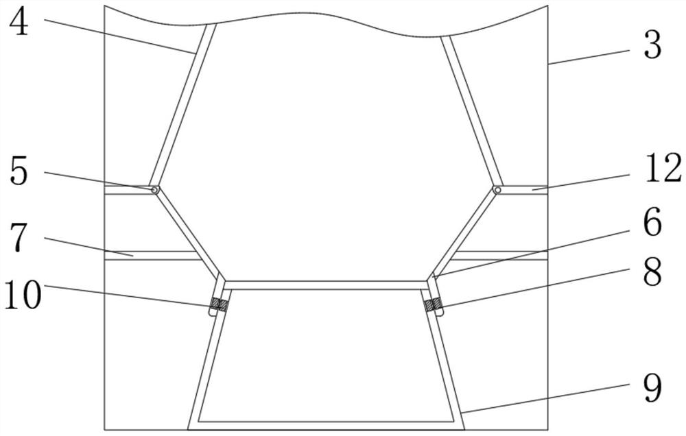
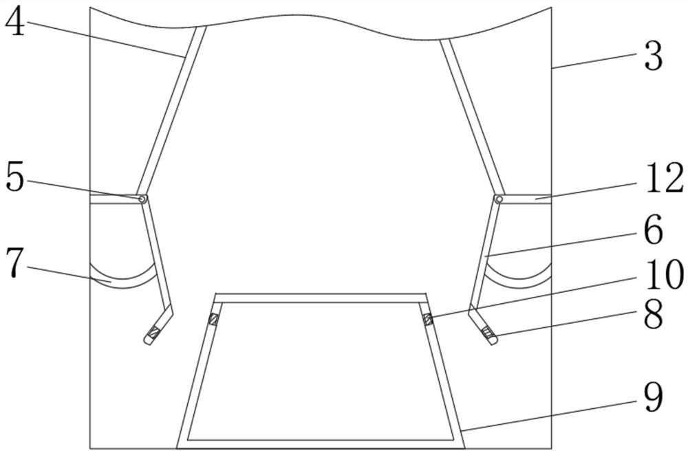
[0019] See Figure 1-4 A high pressure separator, including a can body 1, a feed tube 2, and a feed tube 2 mounted on top of the can body 1, and a tank body is mounted, a cassette 3 is mounted, and the cassette 3 is rectangled, and the cartridge 3 is installed. There is a guide plate 4, which is inverted, facilitating the diffusion of the water flow, so that the area after the flow of water flows into large, the cassette 3 is mounted with a positioning plate 12 at the bottom of the guide plate 4, the positioning plate 12 and...


PUM


Abstract

The invention relates to the technical field of intelligent manufacturing, and discloses a high-pressure separator, which includes a tank body and a feed pipe, the feed pipe is installed on the top of the tank body, a ferrule is installed in the tank body, and the ferrule A deflector is installed inside, and a positioning plate at the bottom of the deflector is installed inside the ferrule. A sliding rod is installed on the end of the positioning plate, and a slanting plate is installed on the sliding rod. In the present invention, by changing the fixed connection of the traditional baffle into an elastic connection, when the liquid passes through the feeding pipe again, the size of the impact force is used to make the ferrule adaptively adjust. The connection between the plate and the guide tube makes the water flow evolve from one vent port to three vent ports, which greatly reduces the force of the water flow when it flows. The design of the elastic connection maximizes the buffering force of the water flow, making the tank body The water flow in the tank tends to be calm, which facilitates the separation of the liquid, and at the same time keeps the liquid separated in a better state.

Description

Technical field [0001] The present invention relates to the field of intelligent manufacturing, in particular a high pressure separator. Background technique [0002] The separator is a machine that separates the mixed substance into two or more different substances. [0003] The working principle of the existing high voltage separator is like Figure 5 The gas-liquid mixed fluid is substantially phase separated by the gas-liquid inlet, and the gas entering the gas passage for gravity settling separation droplets, the liquid into the liquid space separating air bubbles and solid impurities, and the gas is touched before leaving the separator When the aerosol exhes from the vent, the liquid flows out from the outlet, and the liquid flows from the liquid opening. When the liquid is re-entered the separator, the liquid will instantly hit the baffle 11, and the conventional separator is in use, the baffle is hit by the liquid. A portion of the liquid is generated in the phenomenon of ...

Claims


Application Information

Patent Timeline
Patent Type & Authority Patents(China)
IPC IPC(8): B01D19/00B01D21/00B01D21/24
CPCB01D19/00B01D21/00B01D21/2444
Inventor 胡军辉
Owner 山西盛达威科技有限公司
Why Eureka
Try Eureka