A spindle-shaped passive micro-mixer

A spindle-shaped, mixer technology, applied in fluid mixers, mixers, chemical instruments and methods, etc., can solve the problems of complicated processing and manufacturing processes, large pressure drop in microchannels, and violent fluid disturbances, and improve the mixing effect. , increase the contact area and improve the effect of the disturbance effect

Active Publication Date: 2020-05-15
CHINA UNIV OF PETROLEUM (EAST CHINA)
View PDF2 Cites 0 Cited by
  • Summary
  • Abstract
  • Description
  • Claims
  • Application Information

AI Technical Summary

Problems solved by technology

[0004] The inventors have found that the passive micro-mixer with a general two-dimensional structure extends the length of the entire mixer or increases the number of blocking blocks in the channel. This type of passive micro-mixer is simple to process, but the mixing efficiency is low and the mixing channel is long; Passive micro-mixers with complex structures such as passive micro-mixers and chaotic convective passive micro-mixers have severe disturbances to the fluid and good mixing effects, but they have disadvantages such as complicated manufacturing processes and large pressure drop in microchannels.

Method used


Image

  • A spindle-shaped passive micro-mixer
  • A spindle-shaped passive micro-mixer
  • A spindle-shaped passive micro-mixer

Examples


Embodiment 1

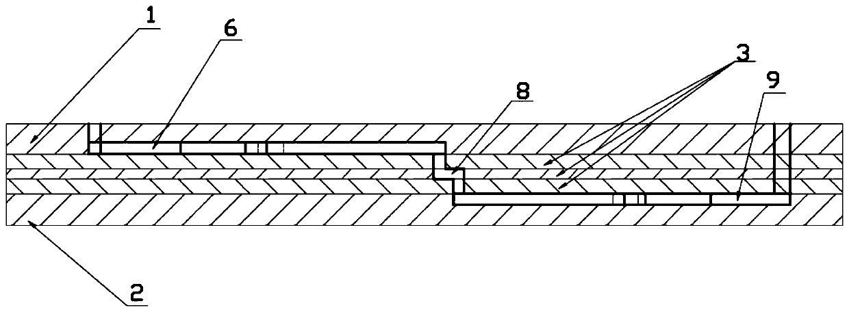
[0035] In a typical implementation of the present application, such as figure 1 As shown, a spindle-shaped passive micro-mixer, a cover plate 1, a base body 3 and a bottom plate 2 are sequentially arranged from top to bottom, and a spindle-shaped mixing unit 7 is respectively arranged on the cover plate and the bottom plate, and the cover plate 1 There is a first inlet channel 4, a second inlet channel 5, a first channel and a spindle-shaped mixing unit 7, the first channel here is a straight channel 6, after the first inlet channel and the second inlet channel merge, through the straight Road 6 communicates with the spindle-shaped mixing unit on the cover plate, and a spindle-shaped mixing unit 7 with the same structure as the spindle-shaped mixing unit on the cover plate is also provided on the base plate, and the first channel is also provided on the base plate, The first passage here is the outlet passage 9, and the third passage is provided on the base body, and the third...

Embodiment 2

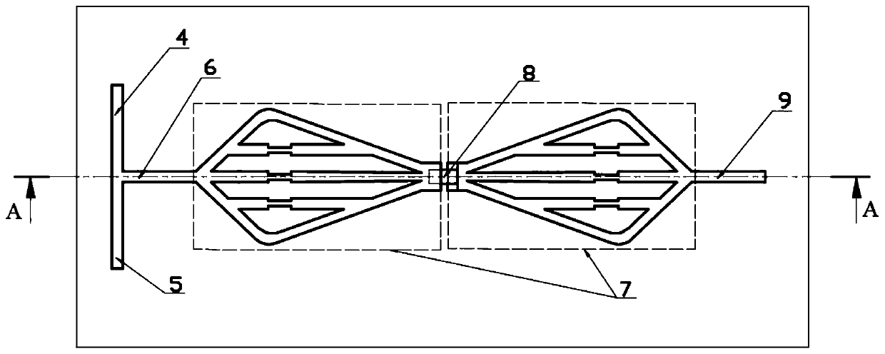
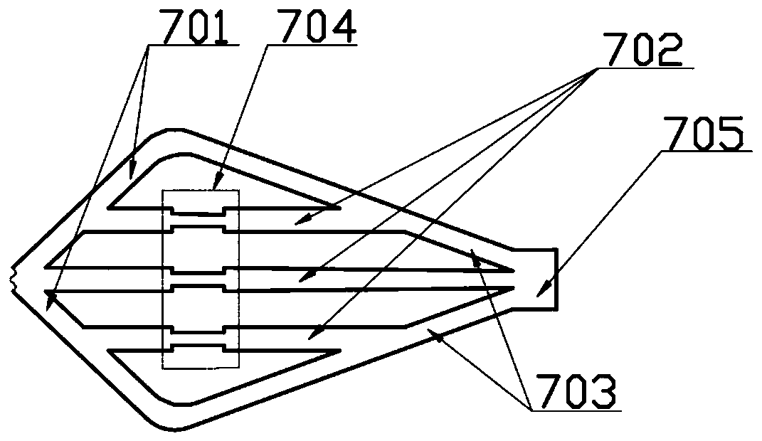
[0042] In the second embodiment of the present application, if figure 2 and image 3 As shown, the difference from Embodiment 1 is the spindle-shaped mixing unit, which includes the second channel and the confluence part 705 connected in sequence; the second channel includes a side channel and a first middle channel, and the side channel has two , arranged in a spindle shape, the intersection point of the short side channel 701 of the two side channels is connected to one end of the first channel, the intersection point of the long side channel 703 of the two side channels is connected to the confluence 705, and the middle channel 702 is connected to the short side The intersection point of and the intersection point of the long side, the first channel, the first intermediate channel and the confluence part 705 have a common axis;

[0043] The second channel also includes a second middle channel 702 provided on each side channel, one end of the second middle channel communic...


PUM


Abstract

The invention discloses a spindle-shaped passive micro-mixer, which comprises a cover plate, a base body and a bottom plate arranged sequentially from top to bottom, the cover plate is provided with a first inlet passage, a second inlet passage and a spindle-shaped mixing unit, the first Both the inlet of the first channel and the inlet of the second channel are connected to the first channel, a spindle-shaped mixing unit is also provided on the bottom plate, a third channel is provided on the base, and one end of the third channel is connected to the spindle-shaped mixing unit on the cover plate, The other end is connected to the spindle-shaped mixing unit on the bottom plate; when flowing in the first channel, relying on molecular diffusion, after mixing, it is divided into multiple channels under the shunting action of the side channel and the middle channel, and mixed separately; it is converging at the confluence part , flows to the spindle-shaped mixing unit on the bottom plate through the third channel, and mixes again, thus improving the mixing effect.

Description

technical field [0001] The invention belongs to the field of micro-mixers, in particular to a spindle-shaped passive micro-mixer. Background technique [0002] As an important part of the microfluidic chip, the micromixer plays a vital role in the microfluidic analysis process. At the microscopic scale, due to the sharp increase of the surface area and volume ratio of the microchannel, the flow velocity of the fluid in the microchannel is generally small, which belongs to the laminar flow at a low Reynolds number. Therefore, the mixing of microfluids can only be realized under the action of intermolecular diffusion at the microscopic scale, and the design of micromixers is very important at this time. [0003] Micromixers can be divided into active micromixers and passive micromixers according to whether the mixing needs to be completed by external power. The active micro-mixer is mainly to disturb the fluid flow field in the micro-channel by setting the energy field drive...

Claims


Application Information

Patent Timeline
Patent Type & Authority Patents(China)
IPC IPC(8): B01F5/06B01F13/00
CPCB01F25/41B01F25/4321B01F25/4323B01F25/4335B01F25/433B01F33/30B01F2101/23
Inventor 牛文杰肖华芝英豪赵淇东杨珊珊孙久洋
Owner CHINA UNIV OF PETROLEUM (EAST CHINA)
Why Eureka
Try Eureka