
a connector

A connector and connecting arm technology, which is applied in the field of rolling stock transmission system, can solve the problems such as the inability to meet the development needs of rail transit vehicles.

Active Publication Date: 2022-03-08
ZHUZHOU TIMES NEW MATERIALS TECH
View PDF8 Cites 0 Cited by
  • Summary
  • Abstract
  • Description
  • Claims
  • Application Information

AI Technical Summary

Problems solved by technology

Traditional rigid connectors or large-size elastic connectors can no longer meet the development needs of rail transit vehicles

Method used


Image

  • a connector
  • a connector
  • a connector

Examples


Embodiment Construction

[0053] The present invention will be further described in detail below in conjunction with the accompanying drawings and specific embodiments, but the protection scope of the present invention is not limited thereby.

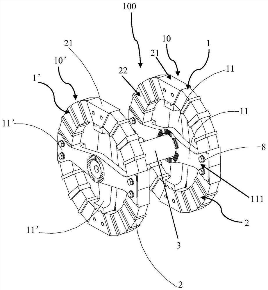
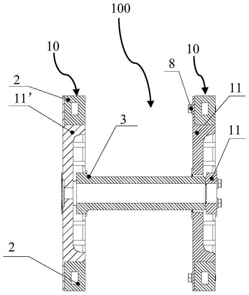
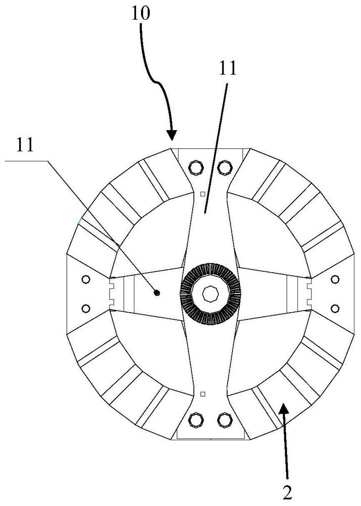
[0054] figure 1 The overall structure of the connector 100 according to the embodiment of the present invention is schematically shown. figure 2 A front view cross-sectional structure of the connector 100 according to the embodiment of the present invention is schematically shown. image 3 A left view structure of the connector 100 according to the embodiment of the present invention is schematically shown. Figure 4 The power transmission state of the connector 100 according to the embodiment of the present invention is schematically shown. Figure 5 The overall structure of the elastic ring 2 of the embodiment of the present invention is schematically shown. Image 6 The split structure of the elastic ring 2 in the embodiment of the present invention is sc...


PUM


Abstract

The invention provides a connector comprising an elastomer unit having two pieces to be connected. Wherein, the pieces to be connected respectively have a connecting arm, and the two connecting arms are arranged opposite to each other and staggered from each other along the axial direction. The end region of the connecting arm is connected to the elastic ring. The connector provided by the invention has a compact structure and occupies little space in the axial direction.

Description

technical field [0001] The invention belongs to the technical field of locomotive and vehicle transmission systems, and in particular relates to a connector. Background technique [0002] In a mechanical system, different mechanical transmission devices require certain components to be connected to transmit motion and torque to the rear. Connectors have good displacement compensation performance and the ability to reduce vibration and noise in mechanical systems, so they are often widely used in the connection of mechanical transmission equipment in industries such as vehicles, ships, lifting, chemicals, and logistics. In the field of rail transit, the requirements for the transmission system of rolling stock are extremely high, and the size of the transmission space is strictly limited. Traditional rigid connectors or large-size elastic connectors can no longer meet the development needs of rail transit vehicles. Contents of the invention [0003] The technical problem ...

Claims


Application Information

Patent Timeline
Patent Type & Authority Patents(China)
IPC IPC(8): F16D3/56F16H57/00
CPCF16D3/56F16H57/00F16D3/78F16D3/68
Inventor 刘文松林胜伍保华罗斌秦中正胡伟辉陆响
Owner ZHUZHOU TIMES NEW MATERIALS TECH
Learn More