
Pneumatic control detecting system for rivets

A detection system and rivet technology, applied in the field of automobile manufacturing, can solve the problems of reduced accuracy, inability to use the detection system, false detection, etc., and achieve the effect of reducing the detection accuracy

Pending Publication Date: 2019-07-09
SAIC-GM-WULING AUTOMOBILE CO LTD
View PDF0 Cites 0 Cited by
  • Summary
  • Abstract
  • Description
  • Claims
  • Application Information

AI Technical Summary

Problems solved by technology

[0003] There are certain limitations in the use of electronic detection technology: first, the welding tooling of the detection station must use an electrical system, so the detection system cannot be used in the sub-assembly and door cover welding line of pure air control; the second is that the proximity switch is Non-contact detection, if there are other metal parts in the sensing range, it is easy to cause false detection, such as the inner plate rivet of the door cover, because the rivet part is too small, the inner plate (metal) where the rivet is installed is likely to interfere with the electric proximity switch. The accuracy of detection is greatly reduced

Method used


Image

  • Pneumatic control detecting system for rivets
  • Pneumatic control detecting system for rivets
  • Pneumatic control detecting system for rivets

Examples


Embodiment Construction

[0018] The present invention will be described in further detail below in conjunction with the accompanying drawings.

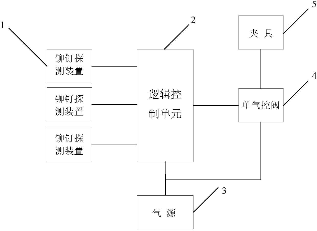
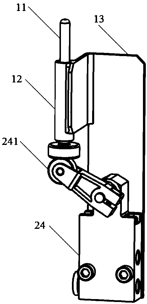
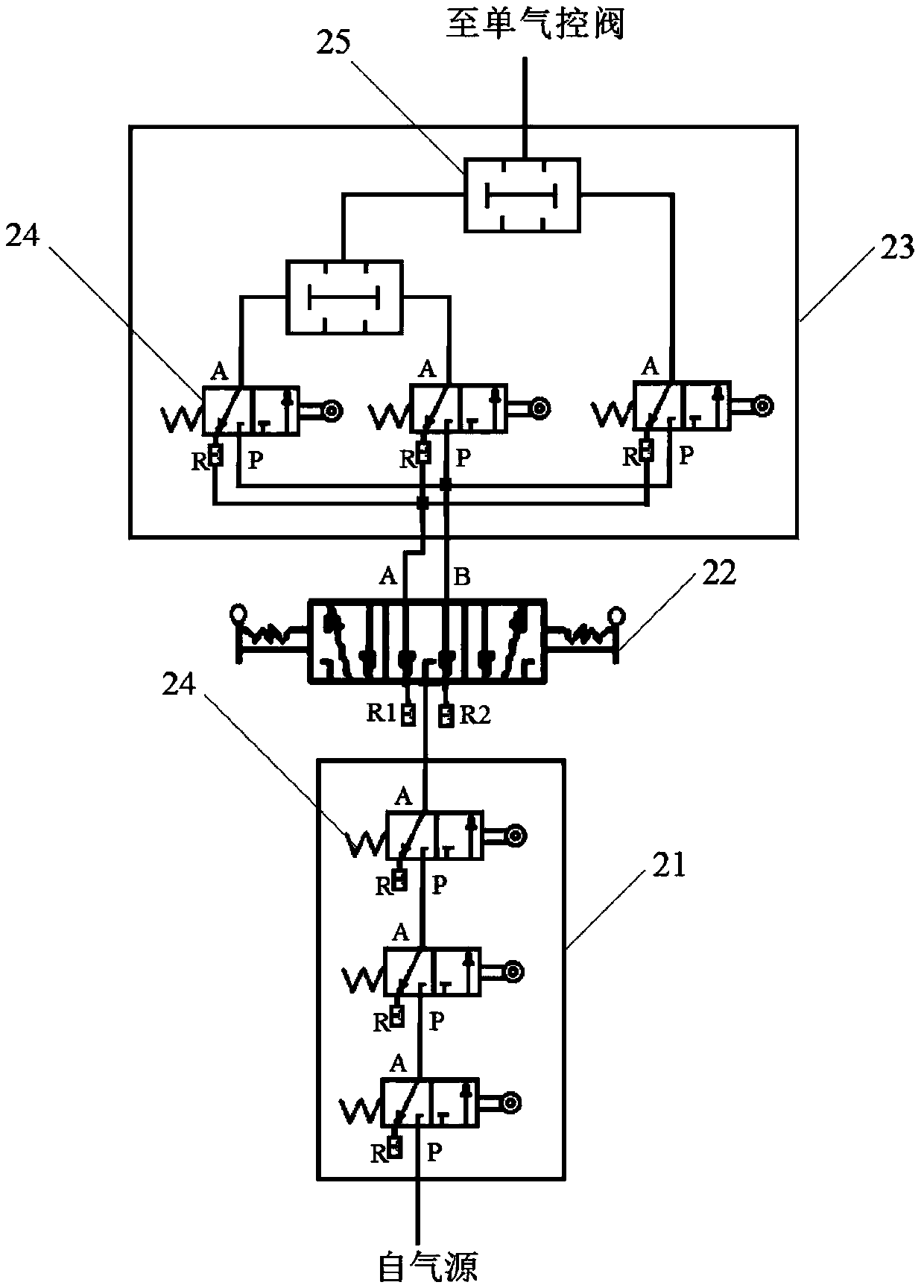
[0019] The structure of a rivet air control detection system in the embodiment of the present invention is as follows: figure 1 As shown, the system includes: a rivet detection device 1 that is in contact with the rivet or the inner plate at the position to be detected, a logic control unit 2 mainly composed of a pneumatic travel switch 24, and a single air valve that connects the air outlet to the main air inlet of the fixture 5. The control valve 4 is connected to the air source 3 connected to the air inlet of the single air control valve 4 , the input end of the logic control unit 2 is connected to the air source 3 , and the output end of the logic control unit 2 is connected to the pilot port of the single air control valve 4 . A rivet detection device 1 is in contact with a swing rod 241 of a pneumatic travel switch 24 of the logic control unit 2, and th...


PUM


Abstract

The invention discloses a pneumatic control detecting system for rivets. The pneumatic control detecting system comprises rivet detecting devices making contact with the rivets at to-be-detected positions or inner plates, a logic control unit mainly constituted by pneumatic travel switches, a single pneumatic control valve with an air outlet being connected with a main air inlet of a clamp, and anair source connected with an air inlet of the single pneumatic control valve; the input end of the logic control unit is connected with the air source, and the output end of the logic control unit isconnected with a pilot port of the single pneumatic control valve; and each rivet detecting device makes contact with a swing rod of the corresponding pneumatic travel switch of the logic control unit, under the effect of the rivets at the to-be-detected positions or the inner plates, the rivet detecting devices enable the pneumatic travel switches to act, and when all the rivets are correctly mounted, the logic control unit outputs an airflow signal to control the single pneumatic control valve to communicate to enable the clamp to be normally closed. A pneumatic detecting technology is adopted, and thus the problem that as for an existing electronic detecting technology for the rivets, due to interference of the metal inner plates, the detecting accuracy rate is decreased is solved.

Description

technical field [0001] The invention relates to automatic detection technology in the field of automobile manufacturing, in particular to an air control detection system for rivets. Background technique [0002] At present, the error-proof detection of automobile body parts generally adopts the electronic detection technology with the proximity switch as the sensor. Most of the body-in-white parts are metal parts. When the parts are installed correctly, the proximity switch can sense the metal parts within a certain distance. There are no rivets in the mounting holes with rivets), over-installation (the rivets should not be installed in the mounting holes with rivets), and wrong installation (the number of rivets installed is correct but the wrong mounting holes are installed). [0003] There are certain limitations in the use of electronic detection technology: first, the welding tooling of the detection station must use an electrical system, so the detection system cannot...

Claims


Application Information

Patent Timeline
Patent Type & Authority Applications(China)
IPC IPC(8): G01V9/00
CPCG01V9/00
Inventor 刘浩程芝群张帝
Owner SAIC-GM-WULING AUTOMOBILE CO LTD
Learn More