Eureka AIR delivers breakthrough ideas for toughest innovation challenges, trusted by R&D personnel around the world.

Novel storage battery housing

A battery and shell technology, applied in the field of new battery shells, can solve the problems of no shock absorption capacity, simple structure, no heat dissipation, etc., to increase or decrease the clamping range, improve safety and stability, improve The effect of anti-collision performance

Inactive Publication Date: 2019-07-09
北京汇生活网络科技有限公司
View PDF6 Cites 5 Cited by
  • Summary
  • Abstract
  • Description
  • Claims
  • Application Information

AI Technical Summary

Problems solved by technology

[0002] A battery is a device that directly converts chemical energy into electrical energy. It is a rechargeable battery designed to be recharged through a reversible chemical reaction. It usually refers to a lead-acid battery, which is a type of battery and belongs to the secondary battery. Battery, its working principle: when charging, the external electric energy is used to regenerate the internal active material, the electric energy is stored as chemical energy, and the chemical energy is converted into electric energy output again when it needs to be discharged, such as mobile phone batteries commonly used in life, etc. When the battery is working It will generate heat, and the normal operation of the battery is greatly affected by the temperature; the common battery casings on the market are simple in structure and single in function. They are made of plastic boxes and do not have the function of heat dissipation. Working in a relatively large environment, and the existing battery case does not have the ability to absorb shocks. Generally, there are usually multiple batteries working at the same time in the industrial site. In order to ensure the normal operation of the battery without collision, it is necessary to improve the shock resistance Anti-collision protection performance, so a battery case with good shock absorption effect and heat dissipation and anti-collision functions is required

Method used


Image

  • Novel storage battery housing
  • Novel storage battery housing
  • Novel storage battery housing

Examples


Embodiment 1

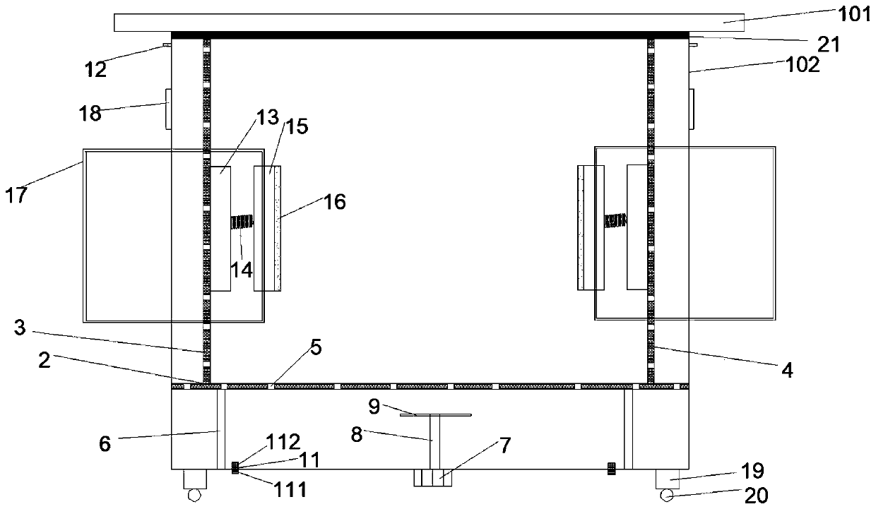
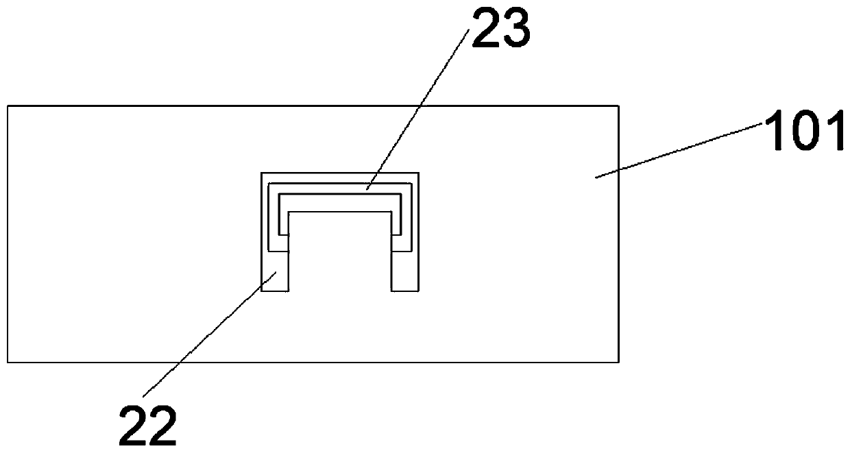
[0030] Such as Figure 1-Figure 6As shown, a new type of storage battery casing includes a casing 102, the top of the casing 102 is provided with a top cover 101, the top cover 101 and the casing 102 are movably connected by hinges, and the upper surface of the top cover 101 is provided with a U The U-shaped groove 22 is provided with a handle 23, which is convenient for the opening and closing of the top cover 101; the inner wall of the lower surface of the housing 102 is fixedly connected with the first baffle 2, and the first A second baffle 3 and a third baffle 4 are vertically arranged on the upper surface of the baffle 2 against the left and right inner walls of the housing 102, and the first baffle 2, the second baffle 3, and the third baffle 4 are all set through. There are several diversion holes 5, and the design of the diversion holes 5 increases the air circulation in the housing 102, which helps to accelerate the heat dissipation of the battery; the lower surface ...

Embodiment 2

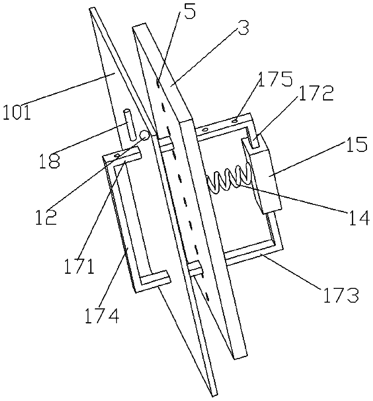
[0032] Such as Figure 1-Figure 6 As shown, this embodiment is a further optimization made on the basis of Embodiment 1. Specifically, the clamping device is provided with pull rods 17, and the pull rods 17 include a first pull rod 171 and a second pull rod 172. , the third pull rod 173, the fourth pull rod 174, the pull rod 17 is an integrated rectangle, the second pull rod 172 vertically runs through the upper and lower side walls of the fixing plate, the fourth pull rod 174 is located outside the housing 102, the first pull rod 171 A number of fixing holes 175 are equidistantly arranged on the top, and the first pull rod 171 and the third pull rod 173 pass through the baffle plate and the side wall of the housing 102 and extend to the outside of the housing 102; the upper end of the pull rod slides on the side wall of the housing 102 A first push rod 18 is provided, and the first push rod 18 matches with the fixing hole 175 on the first pull rod 171 .

[0033] In this embo...

Embodiment 3

[0035] Such as Figure 1-Figure 6 As shown, this embodiment is further optimized on the basis of Embodiment 2. Specifically, the outer wall of the bottom of the housing 102 is provided with a support seat 19, and the lower end of the support seat 19 is fixedly connected with a pulley 20. Brake pads are arranged on the pulley 20 .

[0036] In this embodiment, the support seat 19 and the pulley 20 are provided to facilitate the movement of the present invention, and the operation is convenient.


PUM


Abstract

The invention discloses a novel storage battery housing comprising a shell. A top cover is arranged at the top of the shell. A first baffle plate is fixedly connected on the inner side wall of the lower surface of the shell. A second baffle plate and a third baffle plate are perpendicularly arranged on the upper surface of the first baffle plate near the inner wall of the shell. Multiple flow guide holes are arranged on the first baffle plate, the second baffle plate and the third baffle plate in a penetrating way. A column is perpendicularly arranged on the lower surface of the first baffle plate. A fan is arranged at the bottom outside the shell. A clamping device is arranged on the second baffle plate and the third baffle plate. A pull rod is arranged on the clamping device. Air outletsare arranged on the upper end side walls of the left and right surfaces of the shell in a penetrating way. An air inlet is arranged on the bottom of the shell in a penetrating way. A support base isarranged on the outer side wall of the bottom of the shell. Pulleys are fixedly connected on the lower end of the support base. The air inlet, the air outlets, the fans and the flow guide holes are arranged in the whole process so that the air around the storage battery is always in the accelerated flow replacement state, the purpose of lowering the temperature is achieved and the normal operationof the storage battery is ensured.

Description

technical field [0001] The invention relates to the technical field of accumulators, in particular to a novel accumulator casing. Background technique [0002] A battery is a device that directly converts chemical energy into electrical energy. It is a rechargeable battery designed to be recharged through a reversible chemical reaction. It usually refers to a lead-acid battery, which is a type of battery and belongs to the secondary battery. Battery, its working principle: when charging, the external electric energy is used to regenerate the internal active material, the electric energy is stored as chemical energy, and the chemical energy is converted into electric energy output again when it needs to be discharged, such as mobile phone batteries commonly used in life, etc. When the battery is working It will generate heat, and the normal operation of the battery is greatly affected by the temperature; the common battery casings on the market are simple in structure and sin...

Claims


Application Information

Patent Timeline
Patent Type & Authority Applications(China)
IPC IPC(8): H01M2/10H01M2/08H01M10/613H01M10/623H01M10/6556H01M10/6563B01D46/10H01M50/24H01M50/242H01M50/244H01M50/264H01M50/289
CPCH01M10/613H01M10/623H01M10/6556H01M10/6563B01D46/10H01M50/183H01M50/20H01M50/24Y02E60/10
Inventor 加矿栋
Owner 北京汇生活网络科技有限公司
Why Eureka
Eureka Blog
Learn More