
Ice skate blade bending apparatus

A bending and skating technology, used in skates, skating parts, sports accessories, etc., can solve the problems of time-consuming removal and reassembly, and the design is not widely adopted, and achieves the effect of easy adjustment and easy transportation.

Active Publication Date: 2019-07-09
MAYFLOWER INDUCTRIES LLC
View PDF5 Cites 0 Cited by
  • Summary
  • Abstract
  • Description
  • Claims
  • Application Information

AI Technical Summary

Problems solved by technology

This is problematic because a lot of setting up a skater's skate involves finding a good offset for the blade on the boot; when the blade is removed from the boot, it is often difficult to return the blade to the exact same position during reassembly. Location
Also, removal and reassembly is time consuming
These factors contributed to the design not being widely adopted

Method used


Image

  • Ice skate blade bending apparatus
  • Ice skate blade bending apparatus
  • Ice skate blade bending apparatus

Examples


Embodiment Construction

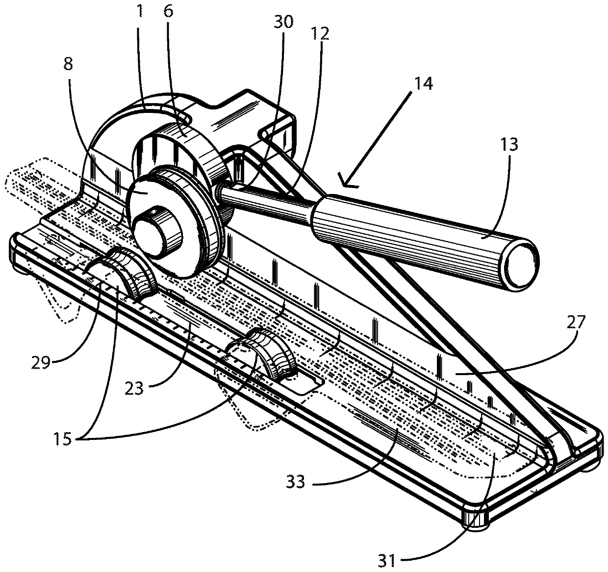
[0080] Referring now to the drawings, there is described a preferred embodiment of a skate blade bending apparatus. It should be noted that the articles "a", "an" and "the" as used in this specification include plural referents unless the content clearly dictates otherwise.

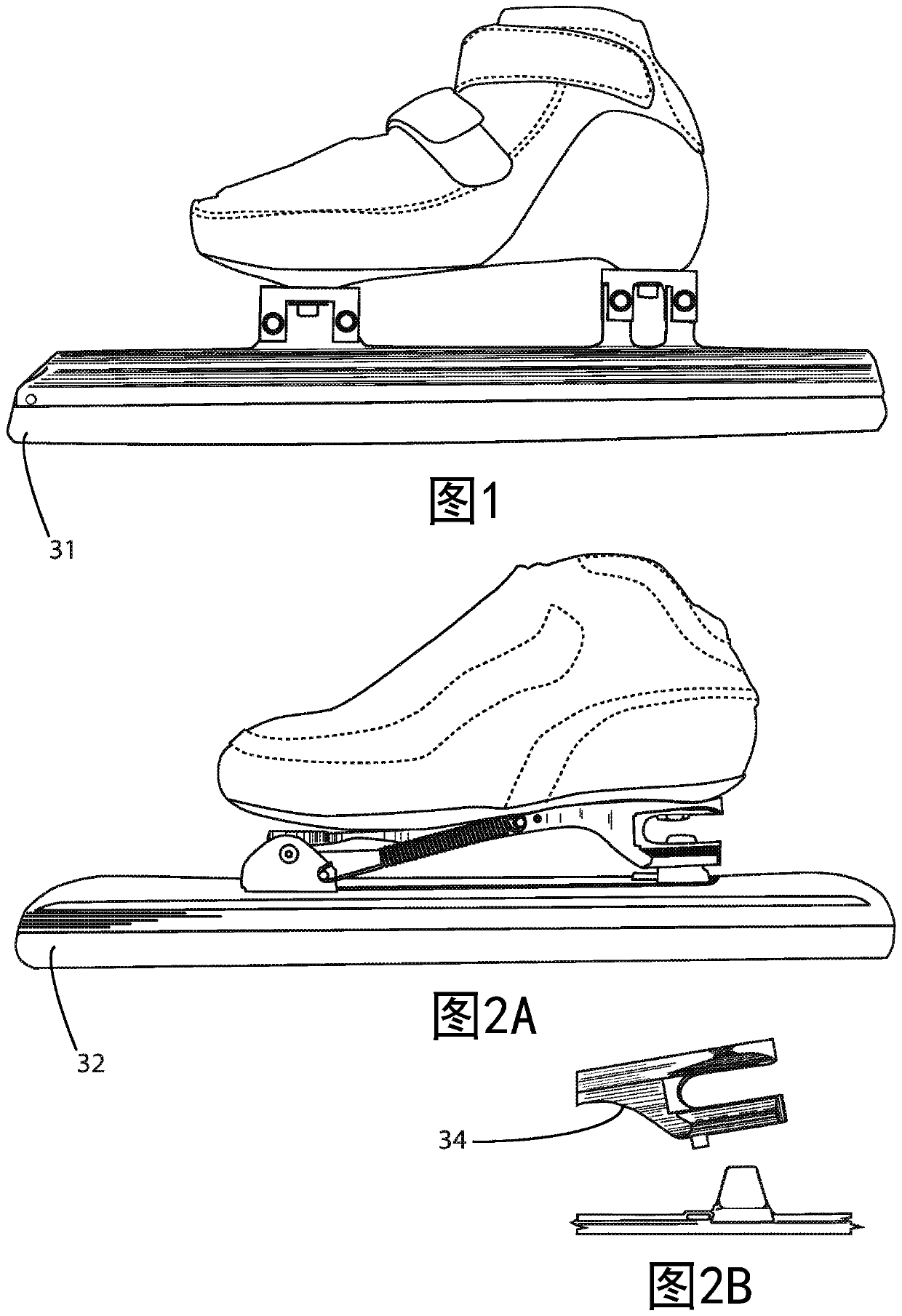
[0081] refer to image 3 and Figure 4 , showing a preferred exemplary embodiment of a blade bending device. The depicted bending apparatus can be used to bend short track skate blades (31) or long track skate blades (32), examples of which are shown in Figures 1 and 2A . Skate blades (31) and (32) are typically provided with an elongated rail-type support (33), which is generally cylindrical and tubular, has appendages to facilitate attachment of blade blade components and mounting points for securing boots, typically Called the skate tube. The blade tube usually has a slot adapted to hold and hold the upper portion of the blade or blade on one side of the blade tube and a mounting platform called a ...


PUM


Abstract

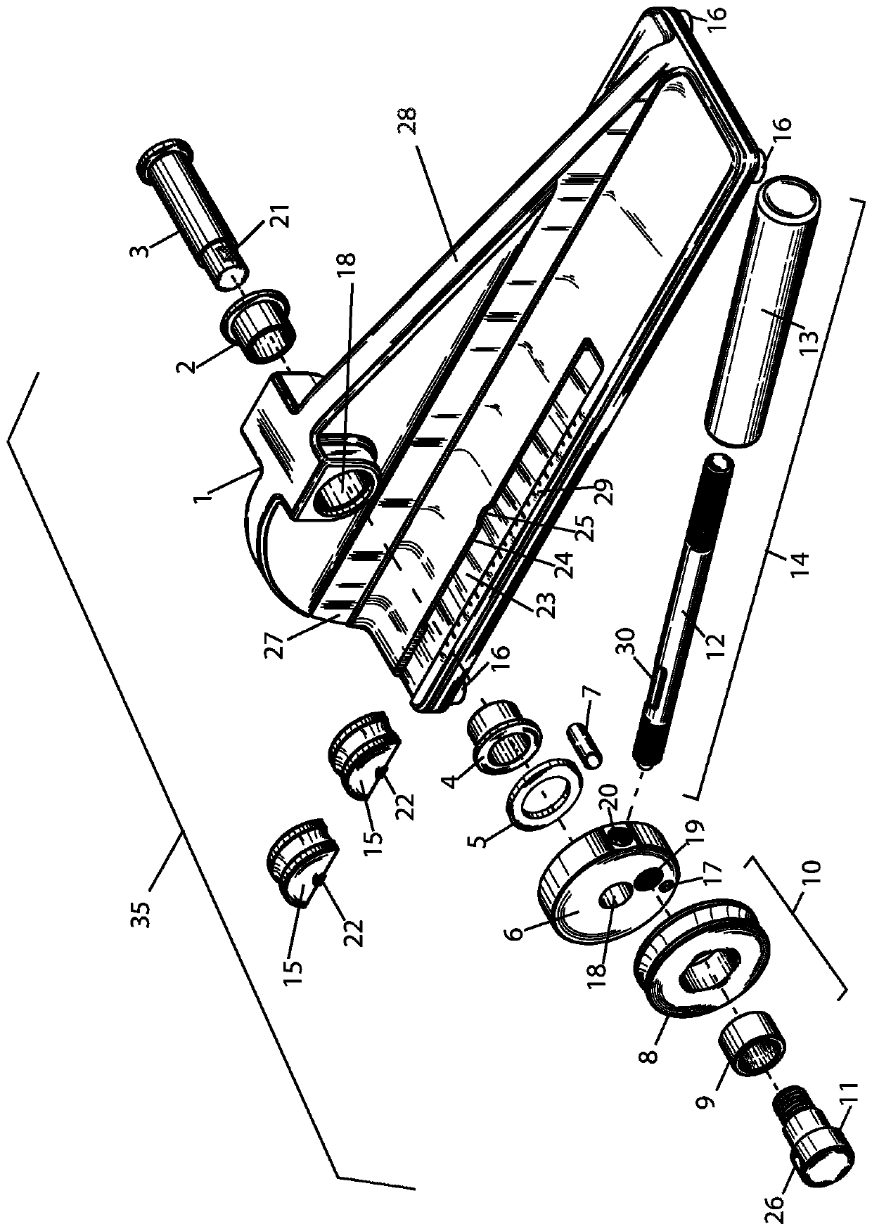
A skate blade bending apparatus (35) may feature a unitary body (1) with a securement structure (10, 15) which holds a skate blade on its side, parallel to the ground, and a means for exerting downward force (8) on the side of the skate blade. The securement structure may feature movable anvils 15 which will change the imparted radius of curvature imparted upon the blade. Indicia (29) may be utilized to position said anvils (15) to ensure the process is repeatable on different blades. A handle (14) used with the means for exerting downward force (8) may be adjustable. The means for exerting downward force (8) and anvils (15) may be interchangeable with other shapes of similar structures for greater versatility.

Description

[0001] Cross References to Related Applications [0002] This application claims priority to U.S. Provisional Application No. 62 / 401,597, filed September 29, 2016, the entire contents of which are incorporated herein by reference. technical field [0003] The invention discussed herein relates to the general field of skating accessories and describes a skate blade bending device. Background technique [0004] Curved speed skate blades were first discussed in US Patent #5,320,368, issued January 14, 1994 to Edmund W. Ling. This patent discusses some of the advantages of the longitudinal side curvature of the speed skating blade and discloses combinations of radii and curvature for the speed skating blade. [0005] Speed ​​skating blades are typically constructed of aluminum or steel longitudinal tubular structures, where the steel blade is mounted on one side of the tube and an aluminum mounting "cup" or "arm" is attached to the opposite side of the tube to allow mounting an...

Claims


Application Information

Patent Timeline
Patent Type & Authority Applications(China)
IPC IPC(8): A63C1/42B21D7/08A63C1/00A63C1/30A63C1/32A63C1/38A63C3/10
CPCA63C1/30A63C1/32A63C1/38B21D7/06B21D11/10A63C1/28A63C1/40
Inventor T·迪纳尔多C·尼达姆M·戈姆C·劳瑞森
Owner MAYFLOWER INDUCTRIES LLC
Learn More