Automatic oral scanning device
An automatic scanning and oral cavity technology, applied in medical science, dentistry, etc., can solve problems such as inability to obtain the shape of oral teeth, troubles, etc., and achieve the effect of compact device, wide application range, and stable and reliable work
- Summary
- Abstract
- Description
- Claims
- Application Information
AI Technical Summary
Problems solved by technology
Method used
Image

Examples
Embodiment Construction
[0019] Referring to the accompanying drawings, through the description of the embodiments, the specific embodiments of the present invention include the shape, structure, mutual position and connection relationship of each part, the function and working principle of each part, and the manufacturing process of the various components involved. And the method of operation and use, etc., are described in further detail to help those skilled in the art have a more complete, accurate and in-depth understanding of the inventive concepts and technical solutions of the present invention.
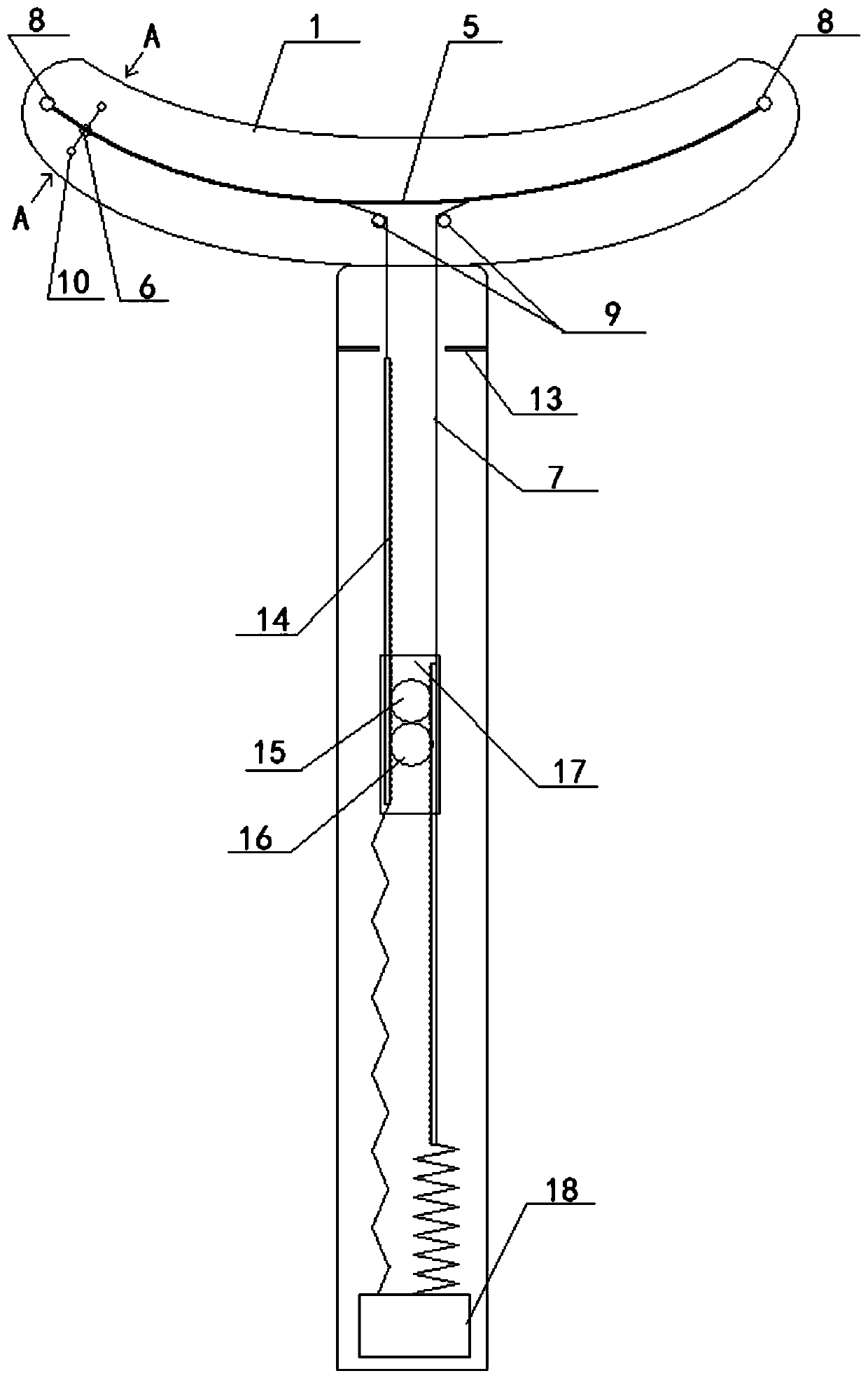
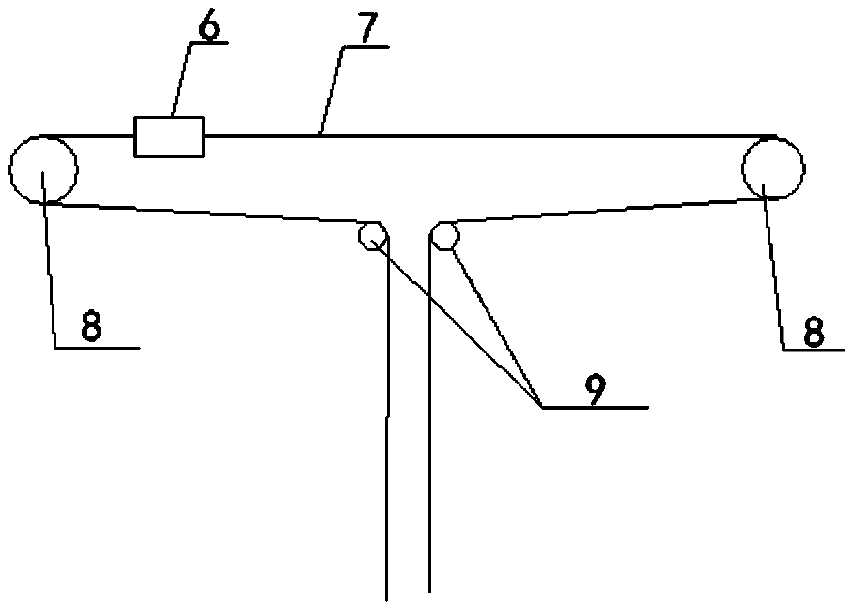
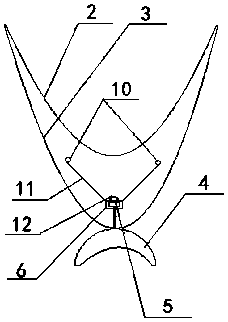
[0020] The oral automatic scanning device is used to scan the oral cavity during dental orthodontic treatment, and transmits the scanned information to the management background in conjunction with the mobile phone, which is used by the background administrator to correct the dental deformity patients. The scanner is equipped with The scanning camera 10 , the electrical signal captured by the camera 1...
PUM
 Abstract
Description
Claims
Application Information
 - R&D
- Intellectual Property
- Life Sciences
- Materials
- Tech Scout
- Unparalleled Data Quality
- Higher Quality Content
- 60% Fewer Hallucinations
Browse by: Latest US Patents, China's latest patents, Technical Efficacy Thesaurus, Application Domain, Technology Topic, Popular Technical Reports.
© 2025 PatSnap. All rights reserved.Legal|Privacy policy|Modern Slavery Act Transparency Statement|Sitemap|About US| Contact US: help@patsnap.com