Self-locking type lifting hook

A self-locking, hook technology, applied in the field of hooks, can solve problems such as troublesome, spring failure, etc., to achieve the effect of convenient use, improve work efficiency, and reduce the steps of manual unhooking

Pending Publication Date: 2019-07-12
广西派莱特科技有限公司
View PDF0 Cites 1 Cited by
  • Summary
  • Abstract
  • Description
  • Claims
  • Application Information

AI Technical Summary

Problems solved by technology

[0002] In the field of logistics, lifting machinery such as cranes are often used to lift goods. When lifting, it is necessary to hook the hook of the hook part to the rope on the goods to be lifted. In order to prevent the rope from detaching from the hook, the existing hook has a self-locking structure, to prevent the rope from slipping from the hook tip, the commonly used self-locking structure is realized by using a spring, but the spring is prone to failure after long-term use, so it is often necessary to replace and maintain the hook, while the spring self-locking form requires manual locking and decoupling, more troublesome

Method used


Image

  • Self-locking type lifting hook
  • Self-locking type lifting hook
  • Self-locking type lifting hook

Examples


Embodiment Construction

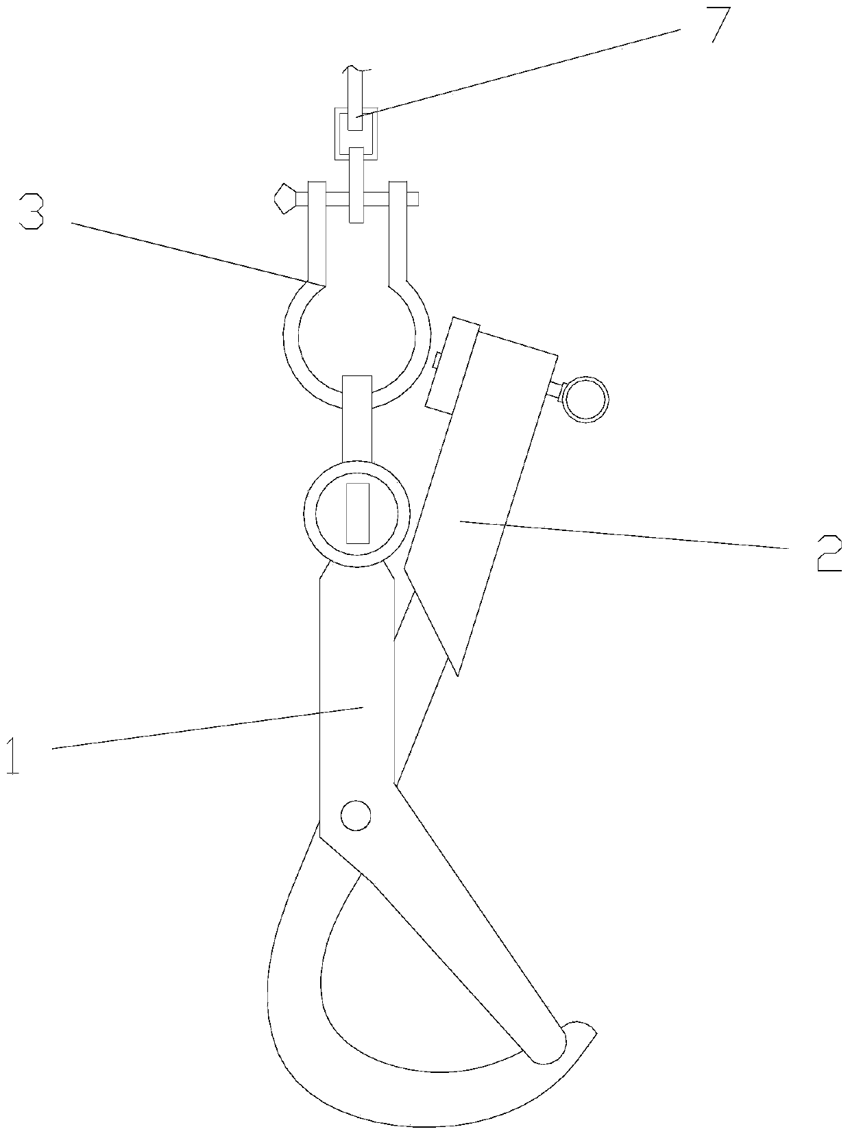
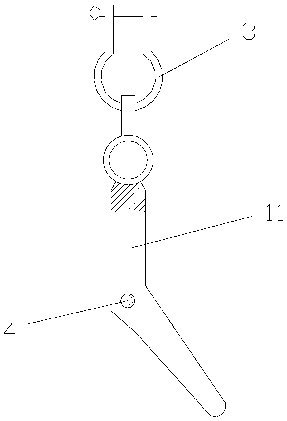
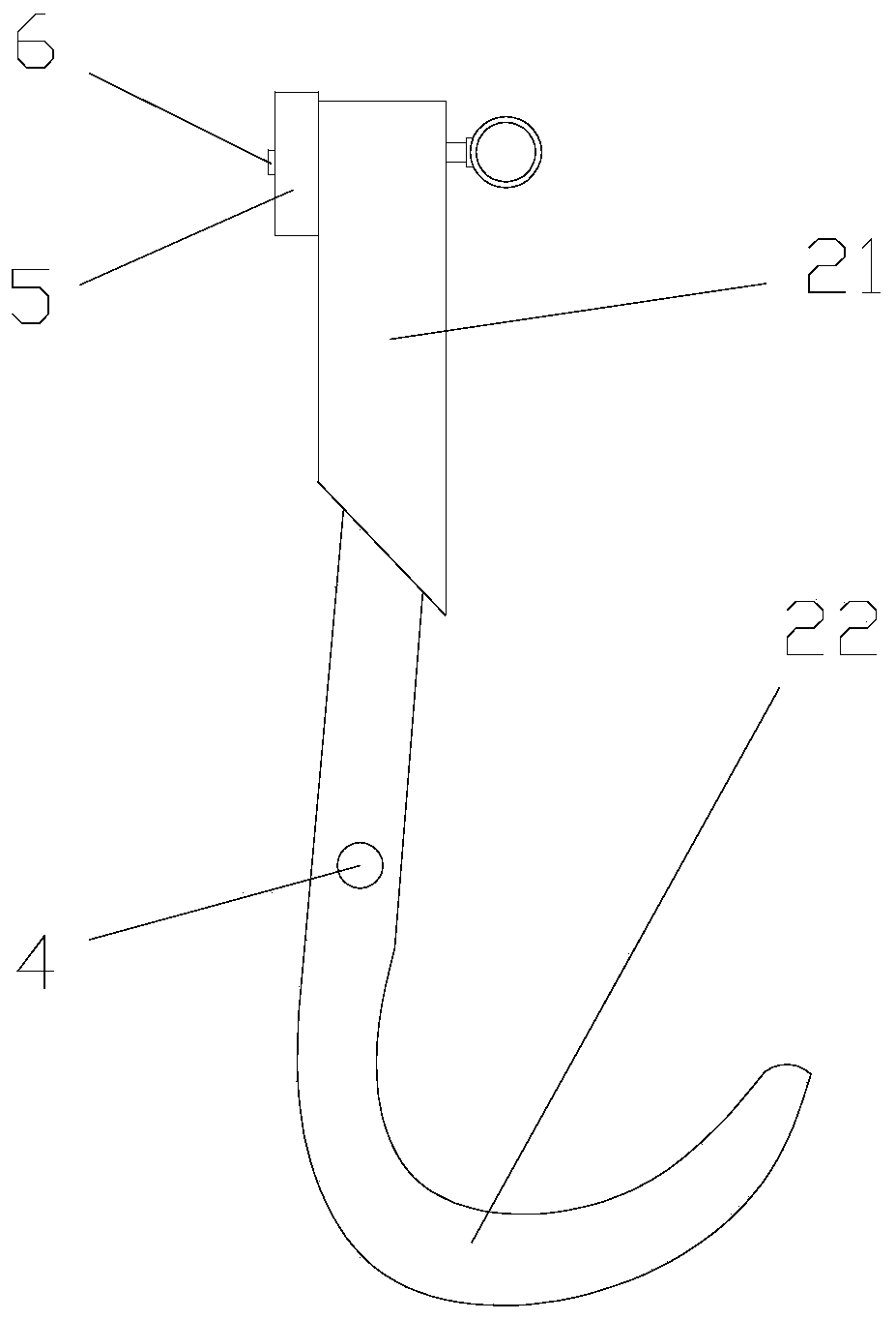
[0023] see Figure 1 to Figure 3 , In a preferred embodiment of the present invention, a self-locking hook includes a fixed hook seat 1 and a movable hook body 2 .

[0024] The top of the fixed hook seat 1 is provided with a connecting part 3 for connecting the external rope 7, the connecting part 3 is a ring structure, and the external rope 7 is one of a rope, a belt, and a chain, so as to connect with the external crane through the connecting part 3. connect.

[0025] The lower part of the fixed hook seat 1 is provided with a through hole 11, and the movable hook body 2 is pierced with the through hole 11, and is connected with the fixed hook seat 1 through the rotating shaft 4 at the through hole 11, and the rotation axis is perpendicular to the described Fix the length direction of the hook seat 1. The movable hook body 2 is divided into a hook portion 22 and a rod portion 21 with the position of the rotating shaft 4 as a dividing point, and the rod portion 21 and the ho...


PUM


Abstract

The invention discloses a self-locking type lifting hook. The self-locking type lifting hook comprises a fixed hook seat and a movable hook body, a connecting part used for being connected with an external rope is arranged at the top of the fixed hook seat, a through hole is formed in the lower part of the fixed hook seat, the movable hook body penetrates through the through hole, and is rotationally connected with the fixed hook seat through a rotating shaft at the through hole; the movable hook body is divided into a hook-shaped part and a rod part by taking the position where the rotating shaft is located as a boundary point, the rod part and the hook-shaped part are arranged on two opposite sides of the fixed hook seat, the weight of the hook-shaped part is smaller than the weight of the rod part, the distance from the end part of the end, far away from the rotating shaft, of the rod part to the rotating shaft is larger than the distance from the end part of the upper end of the through hole to the rotating shaft, the rod part is provided with a magnet at the end which is far away from the rotating shaft, the magnet is installed on the side surface of the side, facing the fixedhook seat connecting part, of the rod part, the magnet and a hook tip of the hook-shaped part are arranged on the two opposite sides of the movable hook body correspondingly, and a suction part is arranged on the side face, facing the side where the magnet located, of the fixed hook seat. According to the self-locking type lifting hook, the unhooking condition of the rope can be effectively prevented, operation of a worker is facilitated, and automatic unhooking can be realized after lifting is finished.

Description

technical field [0001] The invention relates to the technical field of hooks, in particular to a self-locking hook. Background technique [0002] In the field of logistics, lifting machinery such as cranes are often used to lift goods. When lifting, it is necessary to hook the hook of the hook part to the rope on the goods to be lifted. In order to prevent the rope from detaching from the hook, the existing hook has a self-locking structure, to prevent the rope from slipping from the hook tip, the commonly used self-locking structure is realized by using a spring, but the spring is prone to failure after long-term use, so it is often necessary to replace and maintain the hook, while the spring self-locking form requires manual locking And decoupling, more troublesome. Contents of the invention [0003] In view of the above, it is necessary to provide a self-locking hook, which can effectively prevent the rope from being unhooked, is convenient for the staff to operate, an...

Claims


Application Information

Patent Timeline
Patent Type & Authority Applications(China)
IPC IPC(8): B66C1/36B66C1/38
CPCB66C1/36B66C1/38
Inventor 何斌
Owner 广西派莱特科技有限公司
Why Eureka
Try Eureka