Roller energy dissipation device

A technology of energy dissipation device and drum, which is applied in water conservancy projects, marine engineering, coastline protection and other directions, can solve problems such as sluice scour, and achieve the effects of saving renovation costs, low cost and easy operation.

Inactive Publication Date: 2019-07-12
KUNMING UNIV OF SCI & TECH
View PDF13 Cites 2 Cited by
  • Summary
  • Abstract
  • Description
  • Claims
  • Application Information

AI Technical Summary

Problems solved by technology

Therefore, under the sluices, there are generally serious scour phenomena.

Method used


Image

  • Roller energy dissipation device
  • Roller energy dissipation device
  • Roller energy dissipation device

Examples


Embodiment 1

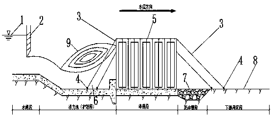
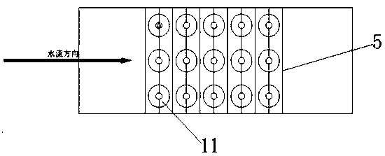
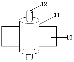
[0018] Embodiment 1: as Figure 1-4 As shown, a drum energy dissipation device includes a drum support frame 5, a drum 11, and a steel shaft 12; wherein the drum support frame 5 is set on the foundation of the sea diffuse section (cooperating with the sea diffuse to eliminate the unremoved water flow in the stilling pool) surplus energy), the steel shaft 12 is installed in the drum support frame 5, and the drum 11 is installed on the steel shaft 12 and rotates with the steel shaft 12.

[0019] Further, it can be set to also include steel chain 3 and steel bar ring 4, the steel bar ring 4 is buried on the foundation of the apron section and the foundation of the downstream river bed 8, one end of the steel chain 3 is connected to the boundary around the drum support frame 5, and the steel chain 3 The other end is connected to the steel ring 4 (such as: two steel chains 3 welding points are respectively arranged on the surrounding borders to weld one end of the steel chain, and ...


PUM


Abstract

The invention discloses a roller energy dissipation device. The roller energy dissipation device comprises a roller supporting frame, a roller and a steel shaft. The roller support frame is arranged on the foundation of the sea flood section, the steel shaft is arranged in the roller supporting frame, and the roller is arranged on the steel shaft to rotate along with the steel shaft. The roller energy dissipation device is arranged behind a stilling basin and is simple in structure, easy to operate and low in manufacturing cost. The roller energy dissipation device can effectively solve the scouring effect of the high-speed water flow on the downstream riverbed of a low-head hydraulic structures (sluices) for retaining water and discharging water in the discharging process, further protectthe riverbed, the riverbank and improve the water flow condition, and save the cost for reinforcing and repairing the riverbank.

Description

technical field [0001] The invention relates to a drum energy dissipation device, which belongs to the field of energy dissipation for sluices of water conservancy and hydropower projects. Background technique [0002] Sluices, as low-head hydraulic structures for retaining and releasing water in water conservancy and hydropower projects, are mostly built on the banks of rivers, canal systems, reservoirs, and lakes. Closing the gates can block floods, block tides, and raise water levels to meet the needs of upstream water diversion and navigation; opening gates can release floods, drain water, flush sand, or adjust flow according to downstream water needs. Sluices are widely used in water conservancy projects. [0003] During the discharge process of the sluice, the potential energy is converted into kinetic energy, and the flow velocity increases. Although most of the excess energy has been eliminated by the water flow through the stilling basin, there is still some excess...

Claims


Application Information

Patent Timeline
Patent Type & Authority Applications(China)
IPC IPC(8): E02B8/06
CPCE02B8/06
Inventor 马荣和董家兴赵毅然李彭飞
Owner KUNMING UNIV OF SCI & TECH
Why Eureka
Try Eureka