Installation structure and construction method of floors

A technology for installing structures and floors, which is applied to building structures, floors, buildings, etc. It can solve the problems affecting the flatness of the floor and the sinking of the floor boards, and achieve the effect of facilitating laying and construction and not being wasteful

Active Publication Date: 2019-07-12
浙江易家建筑工程有限公司
View PDF6 Cites 0 Cited by
  • Summary
  • Abstract
  • Description
  • Claims
  • Application Information

AI Technical Summary

Problems solved by technology

During the solidification period of cement, people may have to walk between the doors in the room. People stepping on the floor boards will cause the floor boards to sink and affect the overall flatness of the floor. There is a big contradiction between the laying of floor boards and people's walking in the room.

Method used


Image

  • Installation structure and construction method of floors
  • Installation structure and construction method of floors
  • Installation structure and construction method of floors

Examples


Embodiment 1

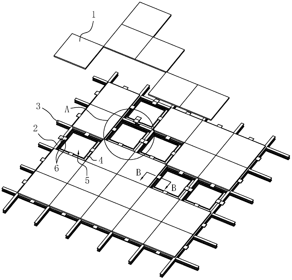
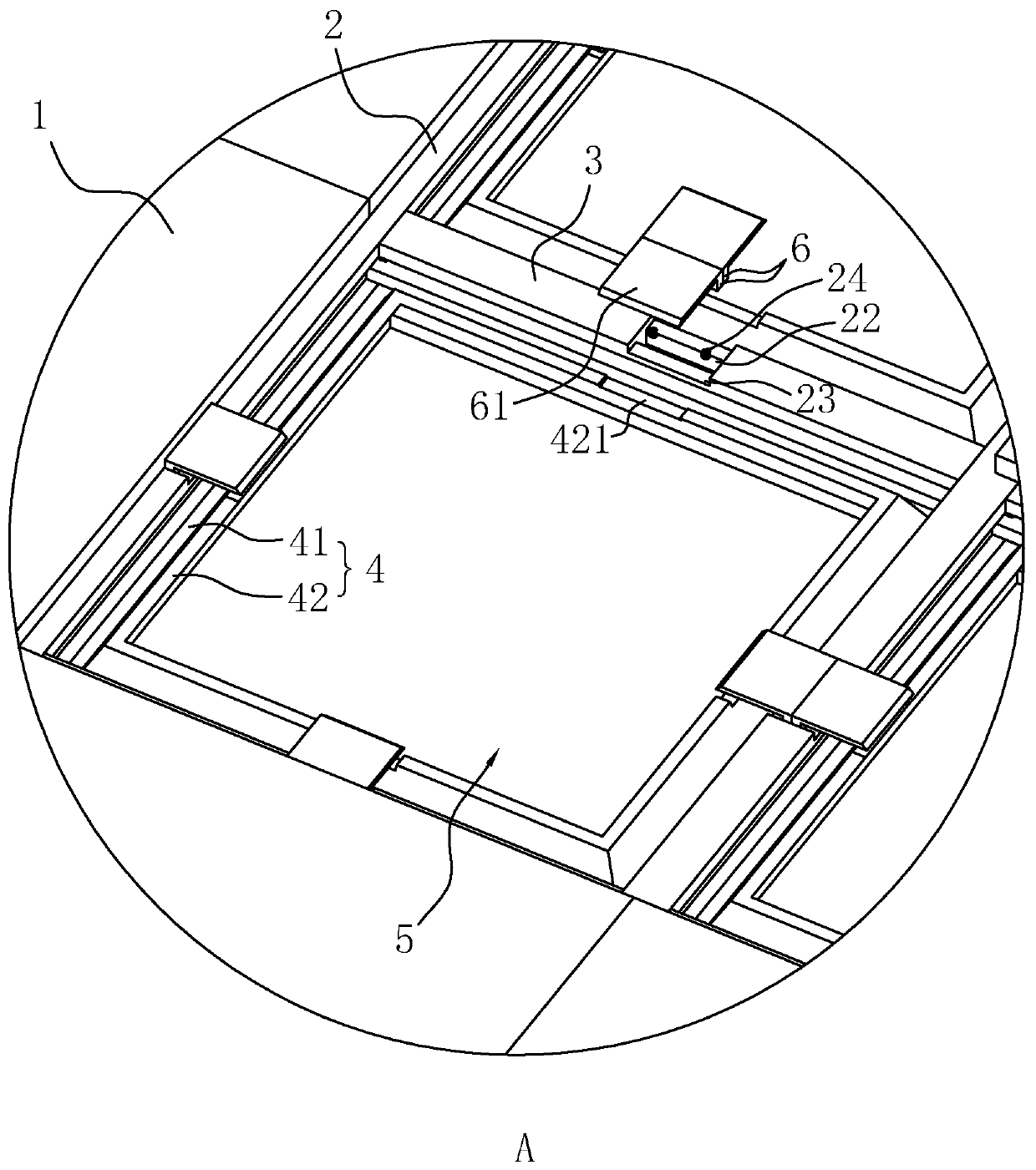
[0042] refer to figure 1 , is a floor installation structure disclosed in the present invention, comprising a floor board 1, a filling frame 4, a longitudinal keel 2 and a transverse keel 3 intersecting each other, and a rectangular installation cavity 5 is formed between the forward keel 2 and the transverse keel 3 , wherein the filling frames 4 are installed in the installation cavity 5 one by one, and the floor boards 1 are installed above the filling frames 4 in a one-to-one correspondence.

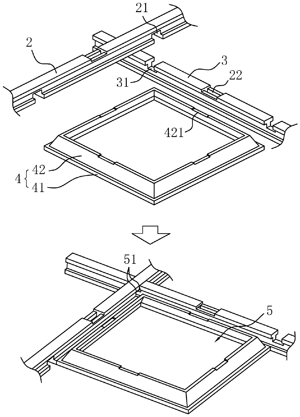
[0043] refer to figure 2 The cross-sectional shapes of the forward keel 2 and the transverse keel 3 along the width direction are both I-shaped, and the lower end surface of the forward keel 2 is provided with a plurality of positioning grooves 121, and the positioning grooves 121 are uniform along the length direction of the forward keel 2 Distribution, the depth of the positioning groove 1 21 is half of the height of the keel 2 along the direction and penetrates through the two side...

Embodiment 2

[0055] A floor construction method, using the above-mentioned floor installation structure, comprising the following steps:

[0056] Step 1: Lay horizontal keels 3 at equal intervals on the ground, and then lay forward keels 2 on the horizontal keels 3. The forward keels 2 and the horizontal keels 3 are interlocked with each other through positioning groove 1 21 and positioning groove 2 31 to form a cross shape.

[0057] Step 2: Install the filling frame 4 in the installation cavity 5, and install the positioning block 6 in the first slot 22.

[0058] Step 3: Personnel determine the position on the ground that does not need to walk according to the required walking range. This position is used to install the first batch of floor boards 1; before installing floor boards 1, inject cement into the side frame 42 and the forward keel 2 In the frame-shaped space between the 3 keels, the floor plate 1, the forward keel 2, and the transverse keel 3 are also coated with cement, and th...


PUM


Abstract

The invention discloses an installation structure and construction method of floors, and relates to the technical field of interior decoration. According to key points of the technical scheme, the installation structure comprises floor blocks, consequent keels and horizontal keels, wherein the consequent keels and the horizontal keels are distributed in a cross mode, rectangular installation cavities are formed between the consequent keels and the horizontal keels, a plurality of pairs of positioning blocks are arranged in the top faces of the consequent keels and the top faces of the horizontal keels in the length direction correspondingly, the four sides of the installation cavities correspond to pairs of positioning blocks correspondingly, the pairs of positioning blocks are arranged side by side in the width direction of the consequent keels or the width direction of the horizontal keels, and the pairs of positioning blocks slidably make a contact through the side walls. Accordingto the installation structure of the floors, the contradiction of laying of the floor blocks and walking of personnel in an indoor room is greatly reduced, and the floors are laid conveniently; and byarranging filling frames, the connection strength of the floor blocks and the consumption of cement are integrated by the installation structure of the floors, and the installation structure of the floors is preferable.

Description

technical field [0001] The invention relates to the technical field of interior decoration, in particular to a floor installation structure and a construction method thereof. Background technique [0002] With the improvement of residents' living standards, the indoor decoration generally adopts the way of laying the floor to replace the concrete floor. The floor makes the ground clean and bright, and has a better decorative effect. Before laying the floor, it is generally necessary to lay keels on the ground. On the one hand, the keel is used to level the ground, and on the other hand, it separates the floor from the ground, which plays a moisture-proof effect for the floor. [0003] The Chinese utility model patent with the authorized notification number of CN204418592U discloses a floor with cross keels, including forward keels, transverse keels, and floor boards. Combined to form a cross keel, the cross keel is covered with a moisture-proof film, and the floor board is ...

Claims


Application Information

Patent Timeline
Patent Type & Authority Applications(China)
IPC IPC(8): E04F15/02
CPCE04F15/02044E04F2015/0205E04F2015/02066
Inventor 王海勇
Owner 浙江易家建筑工程有限公司
Why Eureka
Try Eureka