
Door brake and cabinet

A technology of brakes and door brakes, which is applied to switches with brake devices, door/window accessories, building fastening devices, etc. It can solve the problems of unfixable doors, damage to cabinets and cabinet doors, and large space occupied by brakes. And other issues

Inactive Publication Date: 2019-07-12
STATE GRID HEBEI ELECTRIC POWER CO LTD +1
View PDF7 Cites 2 Cited by
  • Summary
  • Abstract
  • Description
  • Claims
  • Application Information

AI Technical Summary

Problems solved by technology

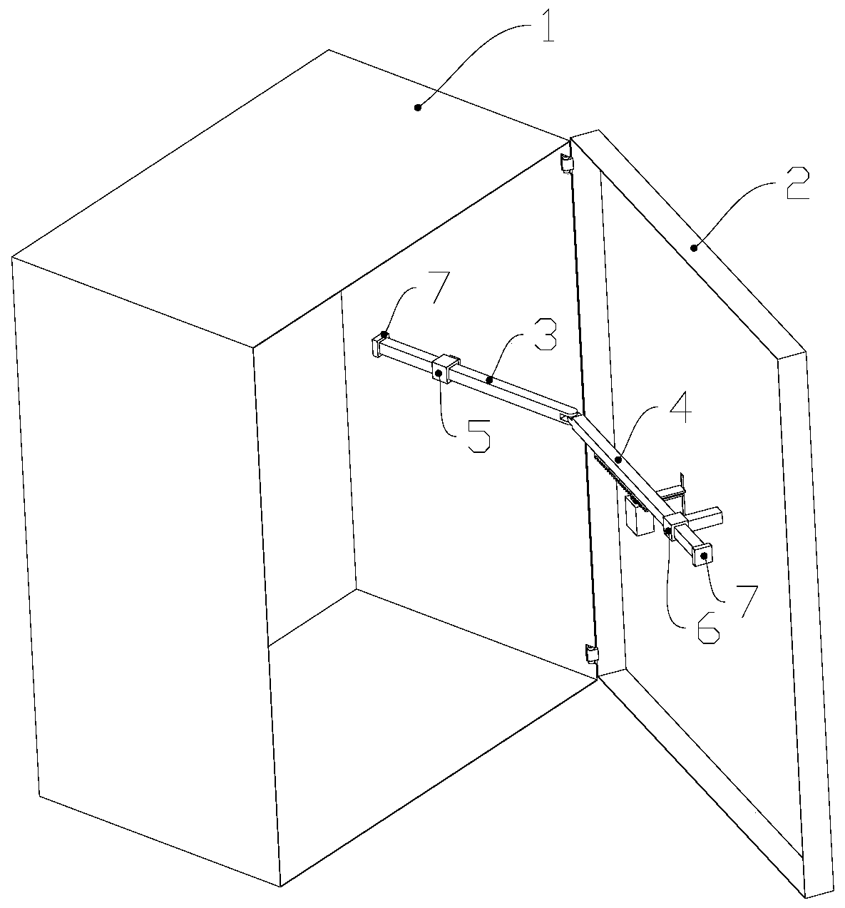
[0003] The purpose of the present invention is to provide a door brake and a cabinet, aiming to solve the problems that the door cannot be fixed after opening, the brake is installed at the hinge, which may easily cause damage to the cabinet body and cabinet door, and the brake takes up too much space during the movement process.

Method used


Image

  • Door brake and cabinet
  • Door brake and cabinet
  • Door brake and cabinet

Examples


Embodiment Construction

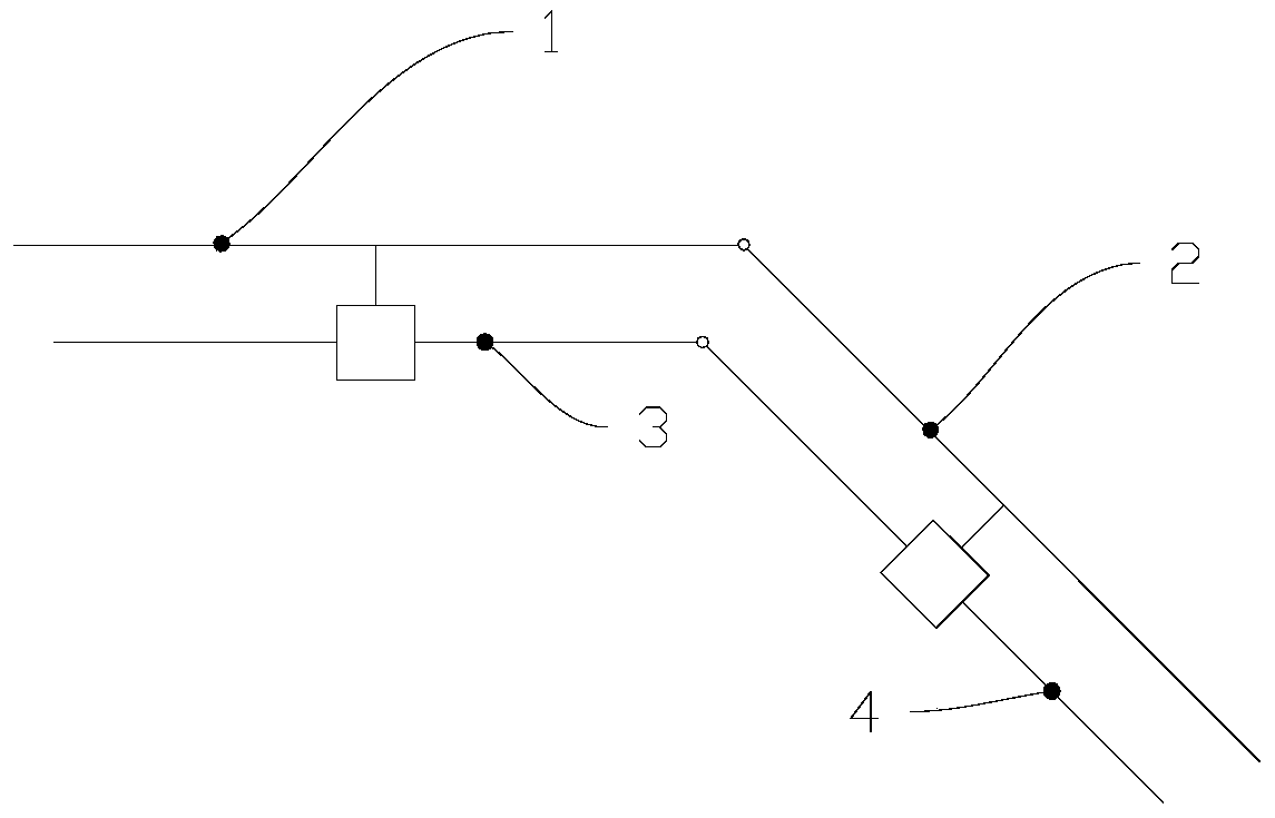
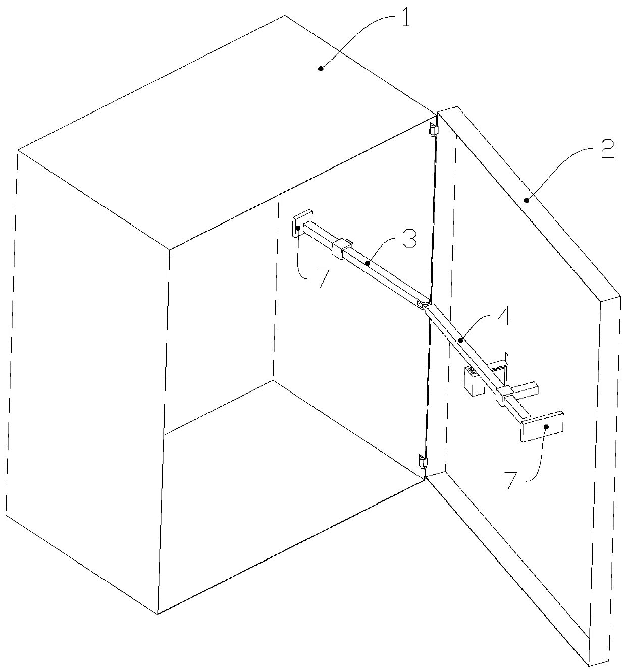
[0028] In order to make the technical problems, technical solutions and beneficial effects to be solved by the present invention clearer, the present invention will be further described in detail below in conjunction with the accompanying drawings and embodiments. It should be understood that the specific embodiments described here are only used to explain the present invention, not to limit the present invention.

[0029] Please also refer to figure 1 , figure 2 and Figure 8 , the door brake provided by the present invention is now described. The door brake includes a first slider 3, the first slider 3 is slidably connected with the side of the cabinet body 1 equipped with the cabinet door 2; a second slider 4, the second slider 4 is slidably connected with the cabinet door 2, and the second One end of the two sliders 4 is rotationally connected with one end of the first slider 3; the first brake block 10, the first brake block 10 is fixedly connected to the first slider...


PUM


Abstract

The invention provides a door brake and a cabinet, and belongs to the technical field of door-window connection. The door brake comprises a first sliding block, a second sliding block, a first brake block and a second brake block, wherein the first sliding block is slidably connected with the side face, provided with a cabinet door, of a cabinet body; the second sliding block is slidably connectedwith the cabinet door, and one end of the second sliding block is rotatably connected with one end of the first sliding block; the first brake block is fixedly connected to the first sliding block orthe second sliding block; and the second brake block is used for being in clamped connection with the first brake block, so that the first sliding block and the cabinet body are fixed relatively or the second sliding block and the cabinet door are fixed relatively. According to the door brake and the cabinet, the problems that the door cannot be fixed after being opened, the cabinet body and thecabinet door are prone to being damaged due to the fact that the brake is mounted at a hinge, and the occupied space is overlarge in the brake motion process are solved.

Description

technical field [0001] The invention belongs to the technical field of door and window connection, and more specifically relates to a door brake and a cabinet. Background technique [0002] The comprehensive power distribution cabinet of distribution transformer is referred to as JP cabinet for short. During the low-voltage power failure, maintenance, emergency repair and installation process of JP cabinet, the door of JP cabinet needs to be opened and closed frequently. In windy weather, when the staff is working, the opened JP cabinet door will often be closed or opened by the wind, which not only brings inconvenience to the operation, but also easily causes scratches or impact injuries to the staff, so it is necessary to Fixes an issue where doors wouldn't snap in place after being opened. Because the cabinet body and cabinet door of the JP cabinet are made of thinner steel plates, it is easy to install the brake on the hinge in the prior art. Under the same external for...

Claims


Application Information

Patent Timeline
Patent Type & Authority Applications(China)
IPC IPC(8): E05C17/32E05F5/08E05C17/34H02B1/30
CPCE05C17/32E05C17/34E05F5/08H02B1/30E05Y2999/00
Inventor 杨书森张文凯徐立双郝亮焦文晶孙国鹏贾占江
Owner STATE GRID HEBEI ELECTRIC POWER CO LTD
Learn More