
Tube tool centering device

A pipe tool, centering technology for centering, applied in the direction of drilling pipe, casing, drilling equipment, etc., can solve the problems of large volume, large space occupation, poor stability and other problems of centralizing devices, and achieve high efficiency, stable operation and high precision Effect

Pending Publication Date: 2019-07-12
SICHUAN HONGHUA PETROLEUM EQUIP
View PDF0 Cites 1 Cited by
  • Summary
  • Abstract
  • Description
  • Claims
  • Application Information

AI Technical Summary

Problems solved by technology

[0003] Usually, the pipe straightening device is used to guide the pipe to the target position between the wellhead (or rat hole) and the pipe conveying device. Guidance and positioning; this kind of righting device is bulky, takes up a lot of space, has poor stability and low efficiency
The other is integrated on the pipe transportation device. The pipe transportation device needs to be run from the pipe yard to the vicinity of the wellhead (or rat hole) on the drill floor, and the pipe is guided to the wellhead (or rat hole) by the pipe centralization device; This centralizing device has poor adaptability, poor stability and low efficiency

Method used


Image

  • Tube tool centering device
  • Tube tool centering device
  • Tube tool centering device

Examples


Embodiment

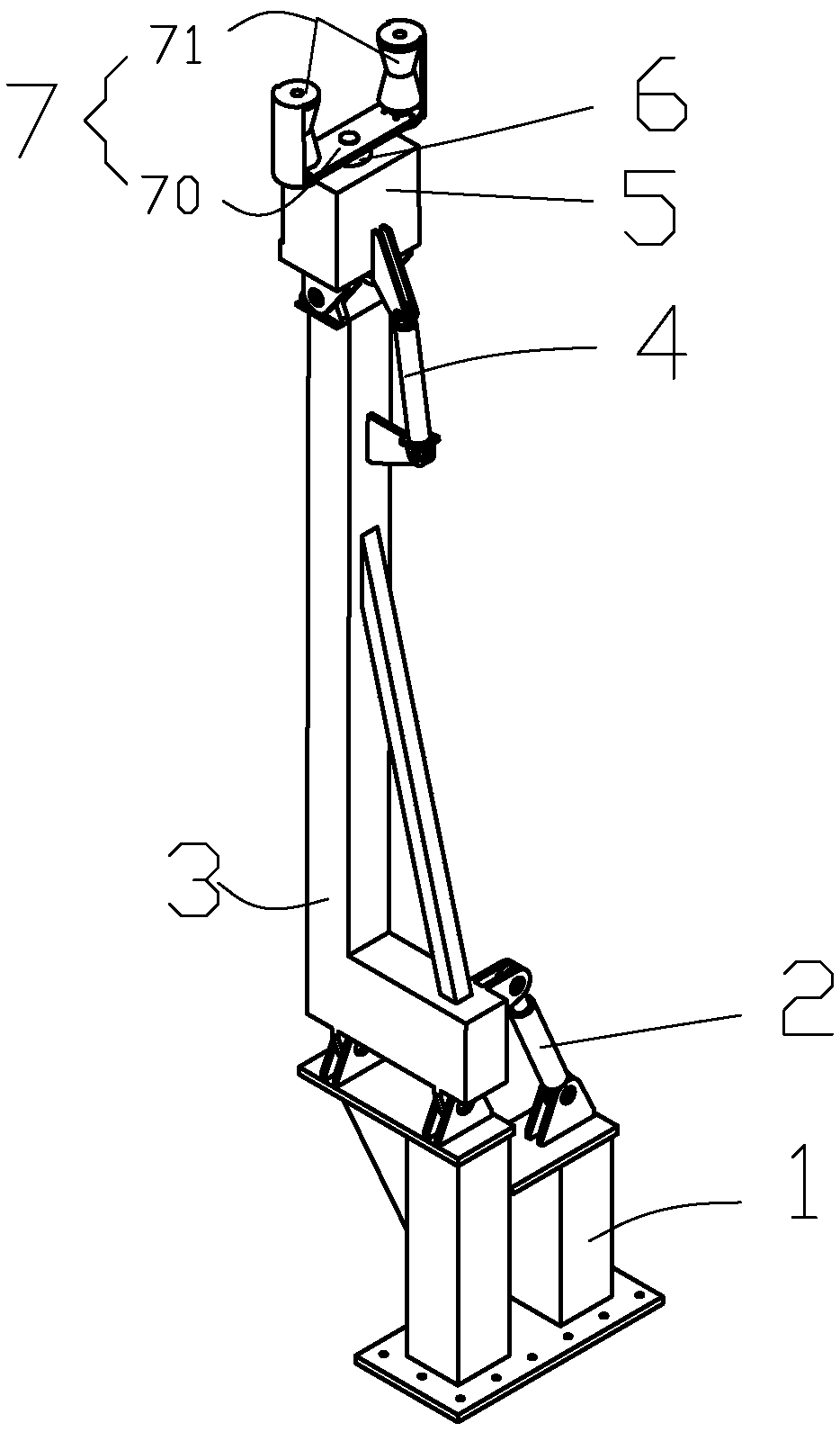
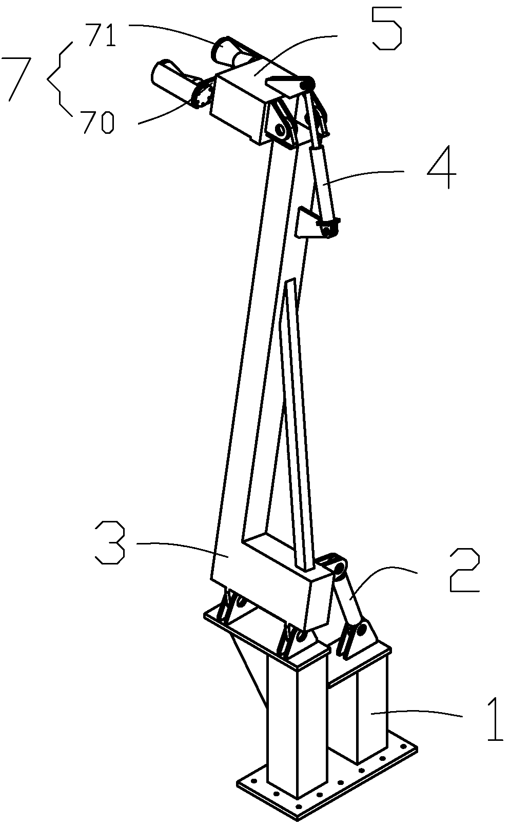
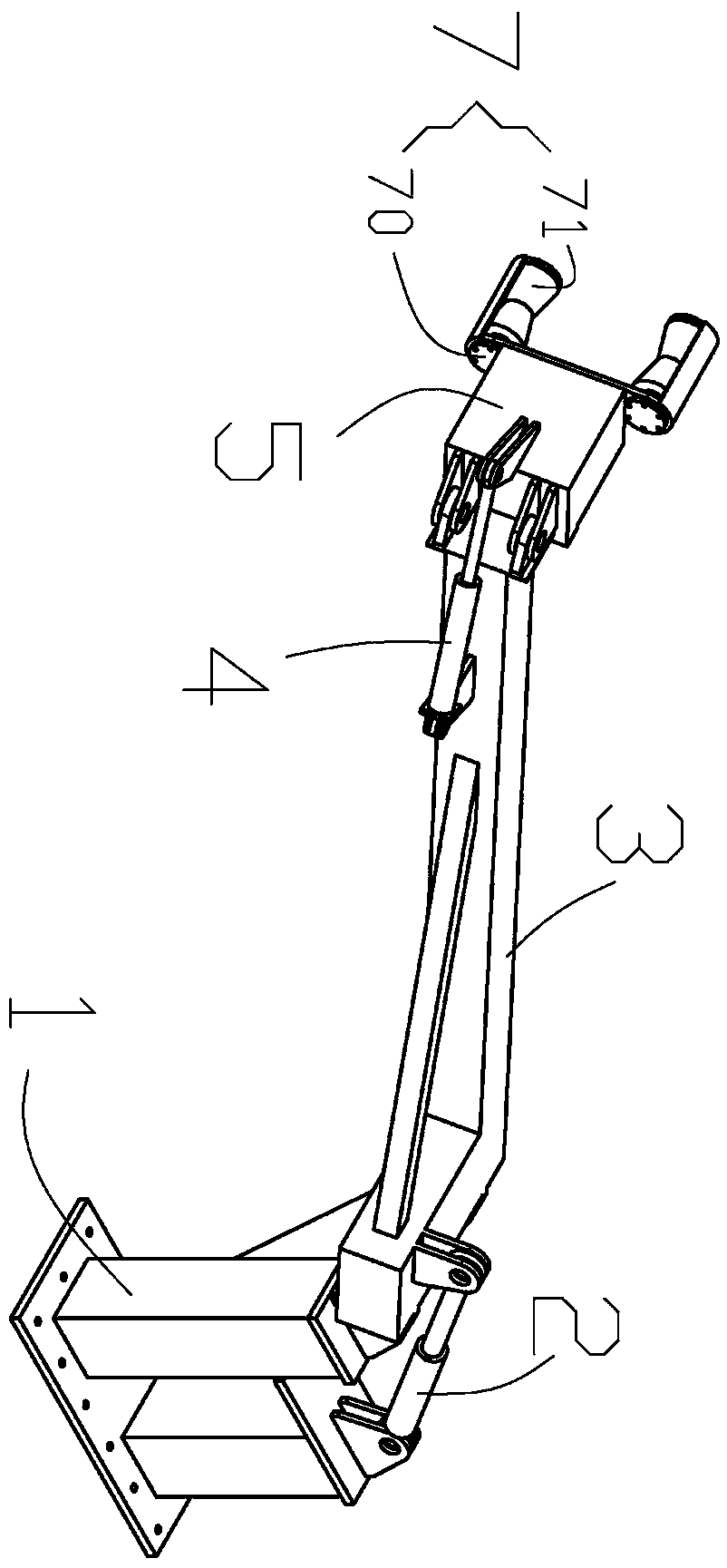
[0031] Such as Figure 1-5 A pipe straightening device shown includes a base 1 , a swing cylinder 2 , a swing arm 3 , a guide cylinder 4 , a guide arm 5 , a rotating motor 6 , and a centering mechanism 7 .

[0032] The swing arm 3 is rotatably connected to the base 1, one end of the swing cylinder 2 is rotatably connected to the base 1, and the other end of the swing cylinder 2 is rotatably connected to the swing arm 3; the guide cylinder 4 is rotatably connected to the swing arm 3; the guide arm One end of 5 is rotatably connected to the swing arm 3, and the other end of the guide arm 5 is rotatably connected to the guide cylinder 4;

[0033] One end of the rotary motor 6 is rotatably connected with the guide arm, and the other end of the rotary motor 6 is fixedly connected with the righting and centering mechanism 7 .

[0034] The righting and centering mechanism 7 includes a support seat 70, at least one roller 71, and the roller 71 is connected with the support seat.

[...


PUM


Abstract

The invention relates to the field of engineering equipment, in particular to a tube tool centering device. The tube tool centering device comprises a base, a swinging hydraulic cylinder, a swinging arm, a guide arm, a guide hydraulic cylinder, a rotary motor and a centering mechanism, the swinging arm is hinged to the base, one end of the swinging hydraulic cylinder is hinged to the base, the other end of the swinging hydraulic cylinder is hinged to the swinging arm, the guide arm is hinged to the swinging arm, one end of the guide hydraulic cylinder is hinged to the swinging arm, the other end of the guide hydraulic cylinder is hinged to the guide arm, one end of the rotary motor is hinged to the guide arm, and the other end of the rotary motor is hinged to the centering mechanism. The rotary motor can drive the centering mechanism to rotate to adjust the centering angle, and the centering mechanism is ensured to be in good contact with tube tools to adapt the tube tools with different diameters; and the guide hydraulic cylinder extends and shrinks to realize the conversion of the working attitude and the waiting attitude, the swinging hydraulic cylinder shrinks to adjust the position, so that the tube tools are centered to another position from one position, as position adjustment is realized through hinged rotation, the size is small, the operation is stable, the precisionis high, the efficiency is high, and the purposes of reducing the cost and improving the efficiency are achieved.

Description

technical field [0001] The invention relates to the field of engineering equipment, in particular to a pipe straightening device. Background technique [0002] In the field of oil and gas, the pipe straightening device is used for pipe straightening and other operations. [0003] Usually, the pipe straightening device is used to guide the pipe to the target position between the wellhead (or rat hole) and the pipe conveying device. Guidance and positioning; this kind of righting device has a large volume, takes up a lot of space, has poor stability, and has low efficiency. The other is integrated on the pipe transportation device. The pipe transportation device needs to be run from the pipe yard to the vicinity of the wellhead (or rat hole) on the drill floor, and the pipe is guided to the wellhead (or rat hole) by the pipe centralization device; This centralizing device has poor adaptability, poor stability and low efficiency. Contents of the invention [0004] In view ...

Claims


Application Information

Patent Timeline
Patent Type & Authority Applications(China)
IPC IPC(8): E21B17/10
CPCE21B17/1078
Inventor 陈崇高杭李志刚唐爱民吴正华
Owner SICHUAN HONGHUA PETROLEUM EQUIP
Learn More