K-edge imaging method

An imaging method and attenuation coefficient technology, applied in the field of X-ray imaging, can solve problems such as poor imaging effect, and achieve the effect of excellent image quality

Active Publication Date: 2019-07-12
INST OF HIGH ENERGY PHYSICS CHINESE ACAD OF SCI
View PDF6 Cites 2 Cited by
  • Summary
  • Abstract
  • Description
  • Claims
  • Application Information

AI Technical Summary

Problems solved by technology

[0006] The purpose of the present invention is to overcome the problem that the method of directly selecting the energy window with the K side as the symmetry axis of the above-mentioned prior art will produce errors, resulting in poor imaging effects, and provide a K side with less error and better imaging effects. imaging method

Method used


Image

  • K-edge imaging method
  • K-edge imaging method
  • K-edge imaging method

Examples


Embodiment Construction

[0051] Example embodiments will now be described more fully with reference to the accompanying drawings. Example embodiments may, however, be embodied in many forms and should not be construed as limited to the embodiments set forth herein; rather, these embodiments are provided so that this disclosure will be thorough and complete, and will fully convey the concept of example embodiments to those skilled in the art. The same reference numerals in the drawings denote the same or similar structures, and thus their detailed descriptions will be omitted.

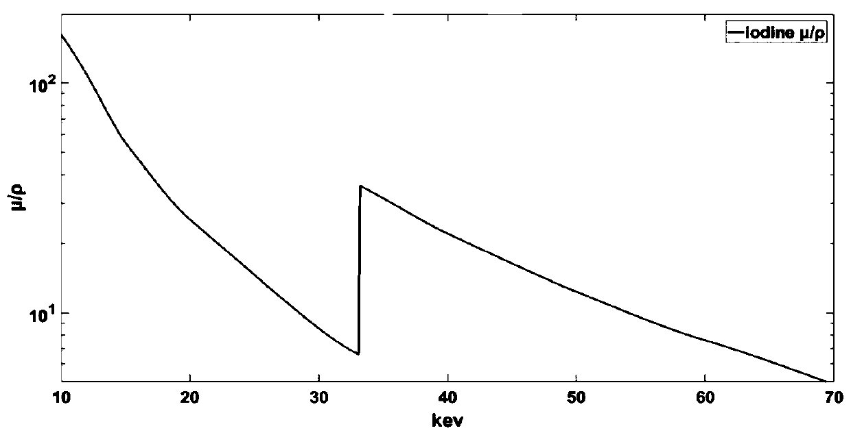
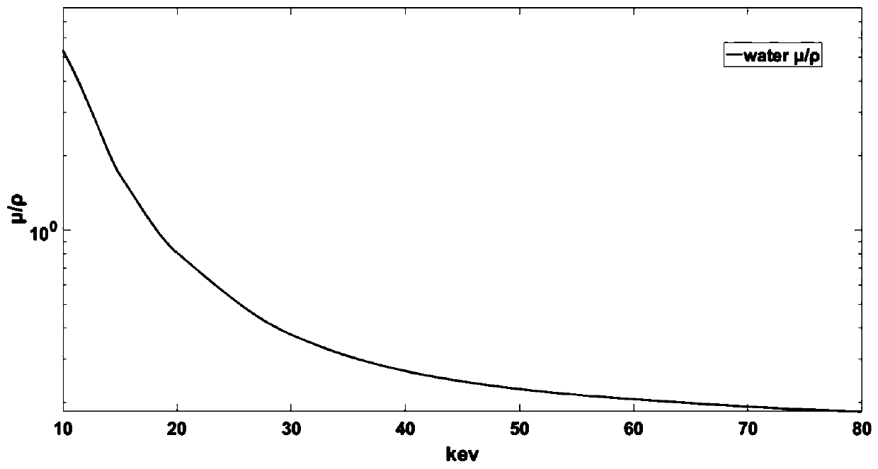
[0052] refer to figure 1 , the material’s absorption of X-rays is mainly photoelectric absorption and Compton scattering effect. The photon energies are also different. For example, iodine in clinically used iodine contrast agent has a specific absorption energy of K-layer electrons of 33.2 keV. Since it has an obvious absorption effect on photons at 33.2 keV, the attenuation at 33.2 keV is shown on the attenuation curve of ...


PUM


Abstract

The invention relates to the technical field of imaging, and provides a K-edge imaging method. The K-edge imaging method comprises the steps of acquiring the energy resolution of a detector, and determining a Gaussian convolution kernel according to the energy resolution; obtaining a theoretical attenuation coefficient curve; obtaining a first smooth attenuation coefficient curve according to theGaussian convolution kernel and the theoretical attenuation coefficient curve; obtaining a second smooth attenuation coefficient curve according to the first smooth attenuation coefficient curve in combination with spectral information in an energy window; and selecting positions of the energy window according to the second smooth attenuation coefficient curve. When the position of the energy window is selected, the influences of the energy resolution of the detector and the spectral information in the energy window are considered, and the positions of the energy window with the maximum attenuation coefficient difference can be well selected under different energy window width requirements, so that subtraction imaging is carried out by using the difference of K-absorption edge as much as possible, and the optimal image quality is obtained.

Description

technical field [0001] The invention relates to the technical field of X-ray imaging, in particular to a K-edge imaging method. Background technique [0002] The location of the energy window can affect the imaging effect when performing X-ray K-edge subtraction imaging. [0003] At present, the method of selecting the energy window in the K-edge subtraction imaging is to directly select the energy window symmetrically around the K-absorption edge of the material. This method of directly selecting the energy window with the K-edge as the axis of symmetry will produce large errors. resulting in poor imaging results. [0004] Therefore, it is necessary to design a new K-edge imaging method. [0005] The above information disclosed in this Background section is only for enhancement of understanding of the background of the invention and therefore it may contain information that does not form the prior art that is already known in the art to a person of ordinary skill in the a...

Claims


Application Information

Patent Timeline
Patent Type & Authority Applications(China)
IPC IPC(8): G01N23/083G01N23/20066
CPCG01N23/083G01N23/20066
Inventor 张志都王哲魏存峰王燕芳许琼李默涵程志威魏龙
Owner INST OF HIGH ENERGY PHYSICS CHINESE ACAD OF SCI
Why Eureka
Try Eureka