
Zoom lens and imaging apparatus

一种变焦透镜、透镜的技术,应用在光学元件、仪器、光学等方向,能够解决难以构成小型的透镜系统、像差变动大、难以确保高画质等问题

Active Publication Date: 2019-07-12
FUJIFILM CORP
View PDF9 Cites 4 Cited by
  • Summary
  • Abstract
  • Description
  • Claims
  • Application Information

AI Technical Summary

Problems solved by technology

[0006] However, the zoom lens described in Patent Document 1 has a problem that even if it is considered on the basis of the size of the imaging element, it is difficult to configure a compact lens system due to the long back focal length and the total length of the lens.
In addition, the zoom lens described in Patent Document 2 has a problem in that aberration fluctuations during focusing are large, so it is difficult to ensure high image quality from a distant view to a close view.

Method used


Image

  • Zoom lens and imaging apparatus
  • Zoom lens and imaging apparatus
  • Zoom lens and imaging apparatus

Examples


Embodiment 1

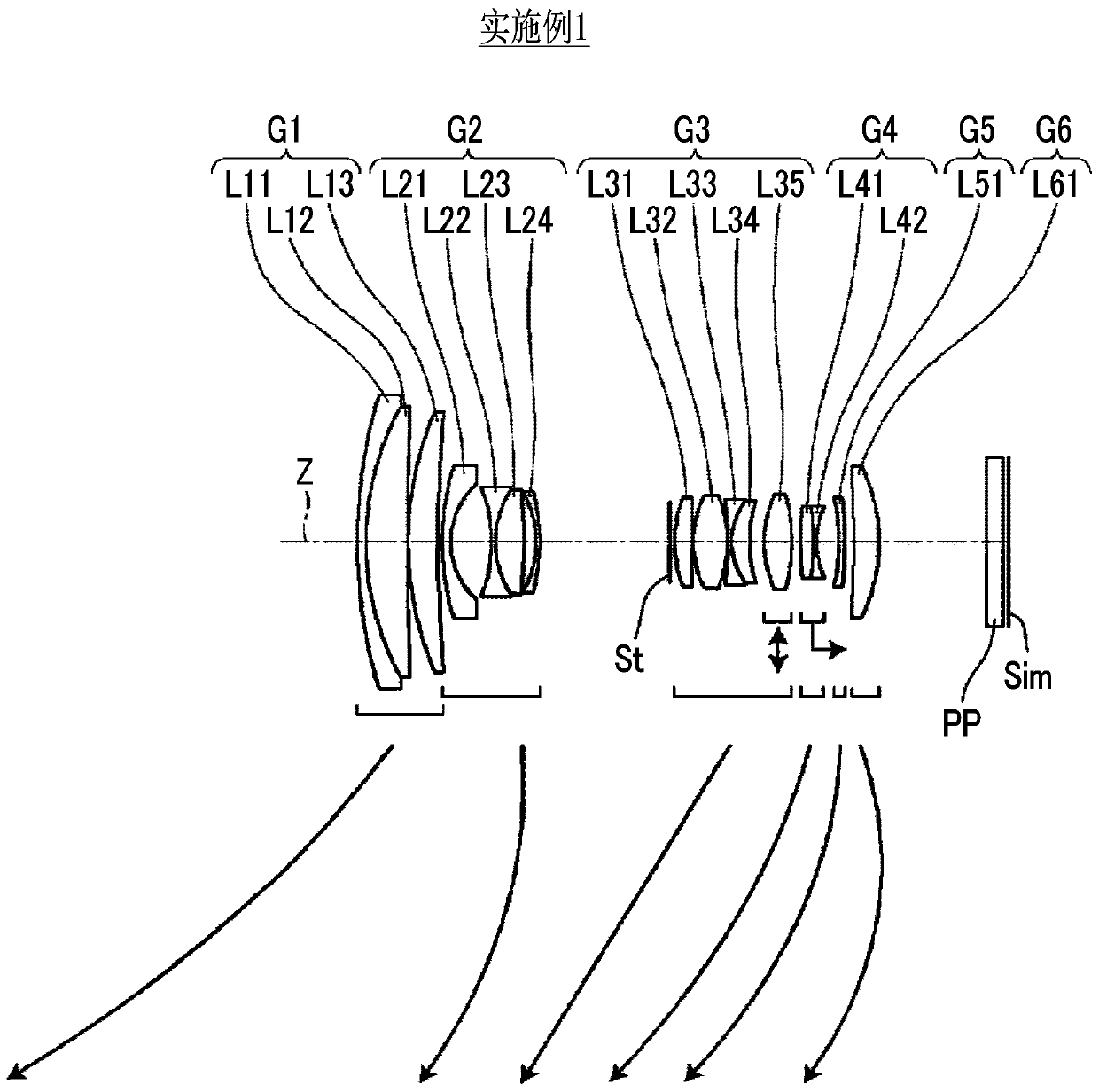
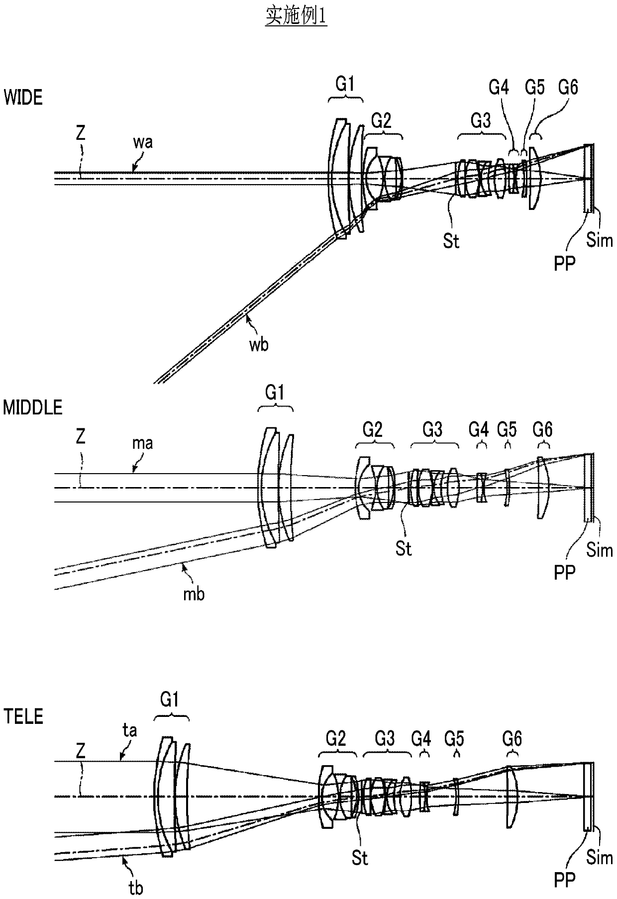
[0105] exist figure 1 and figure 2 A cross-sectional view of the zoom lens of Example 1 is shown in , and the illustration method is as described above, so a part of repeated description is omitted here. The zoom lens of Example 1 consists of the first lens group G1 having positive refractive power, the second lens group G2 having negative refractive power, the aperture stop St, the third lens group G3 having positive refractive power, and the third lens group G3 having positive refractive power from the object side toward the image side. The fourth lens group G4 having a refractive power, the fifth lens group G5 having a negative refractive power, and the sixth lens group G6 having a positive refractive power are constituted. When changing magnification, all the lens groups move in the direction of the optical axis on different trajectories, and the aperture stop St moves integrally with the third lens group G3. The first lens group G1 is composed of three lenses, lenses L...

Embodiment 2

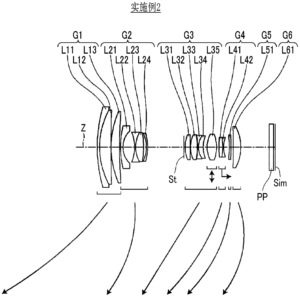
[0131] A sectional view of the zoom lens of Example 2 is shown in image 3 middle. The zoom lens of Example 2 has the same structure as that of the zoom lens of Example 1 in outline. The basic lens data of the zoom lens of Example 2 are shown in Table 4, the specifications and variable surface spacing are shown in Table 5, and the aspheric coefficients are shown in Table 6. The aberration diagram is shown in Figure 9 , each aberration diagram of the state of focusing on an object at a distance of 1.5m (meters) from the image plane Sim is shown in Figure 10 middle.

[0132] [Table 4]

[0133] Example 2

[0134] sn R D Nd vd θgF 1 89.36116 1.500 1.64769 33.79 0.59393 2 48.66208 7.184 1.49700 81.61 0.53887 3 624.11772 0.150 4 55.66700 5.285 1.53775 74.70 0.53936 5 251.45782 DD[5] *6 73.69591 1.400 1.85400 40.38 0.56890 *7 14.22386 7.396 8 -24.86145 0.710 1.56384 60.67 0.5403...

Embodiment 3

[0142] A sectional view of the zoom lens of Example 3 is shown in Figure 4 middle. The zoom lens of Example 3 has the same configuration as that of the zoom lens of Example 1 in outline. Table 7 shows the basic lens data of the zoom lens of Example 3, Table 8 shows the specifications and the distance between variable surfaces, and Table 9 shows the aspheric coefficients. Each aberration diagram is shown in Figure 11 , each aberration diagram of the state of focusing on an object at a distance of 1.5m (meters) from the image plane Sim is shown in Figure 12 middle.

[0143] [Table 7]

[0144] Example 3

[0145] sn R D Nd vd θgF 1 84.35548 1.500 1.66680 33.05 0.59578 2 49.86137 7.135 1.49700 81.61 0.53887 3 914.30159 0.150 4 55.41642 5.088 1.49700 81.61 0.53887 5 219.05663 DD[5] *6 77.54738 1.400 1.85400 40.38 0.56890 *7 14.00511 7.482 8 -23.40369 0.710 1.51742 52.43 0.5564...


PUM


Abstract

The invention provides a high-performance zoom lens which is high in magnification, small in size and capable of well correcting aberration in a zoom full area and in a range from a distant view to aclose view, and an imaging device provided with the zoom lens. The zoom lens includes a positive first lens group (G1), a negative second lens group (G2), a positive third lens group (G3), a negativefourth lens group (G4), a negative fifth lens group (G5), and a positive sixth lens group (G6) in order from an object side. All distances between adjacent lens groups change during zooming. The firstlens group (1) consists of a negative lens, a positive lens, and a positive lens in order from the object side. Only the fourth lens group (G4) moves to an image side during focusing from a long range to a short range. Conditional Expression is related to lateral magnification of the fourth lens group (G4) and a lateral magnification of the sixth lens group (G6) is satisfied.

Description

technical field [0001] The invention relates to a zoom lens and an imaging device. Background technique [0002] Conventionally, in an interchangeable lens used in a digital camera or the like, a high-magnification zoom lens capable of shooting images with a single lens without changing lenses from a so-called wide-angle range to a telephoto range has been demanded. For example, Patent Document 1 and Patent Document 2 described below describe a high-magnification zoom lens that can be used in a digital camera or the like. [0003] Patent Document 1: Japanese Patent Laid-Open No. 2017-134302 [0004] Patent Document 2: Specification of Japanese Patent No. 6189637 [0005] The above-mentioned high-magnification zoom lens that does not require lens replacement is convenient for use in situations where it is not desirable to carry a plurality of lenses, that is, it is not desired to increase luggage, and thus a compact zoom lens is required. In addition, the above-mentioned h...

Claims


Application Information

Patent Timeline
Patent Type & Authority Applications(China)
IPC IPC(8): G02B15/16
CPCG02B15/16G02B15/1461G02B9/62G02B27/0025G02B13/06G02B5/005G02B13/009G02B15/14G02B15/146G02B13/002G02B15/20G02B15/15G02B15/22G02B27/646
Inventor 野田大雅
Owner FUJIFILM CORP
Learn More