Mobile payment method and device and electronic device

A mobile payment and collection device technology, applied in the field of payment, can solve the problems of non-utilization, long time, low efficiency, etc., and achieve the effect of shortening response time, improving payment efficiency, and reducing payment time.

Inactive Publication Date: 2019-07-12
ADVANCED NEW TECH CO LTD
7 Cites 2 Cited by

AI-Extracted Technical Summary

Problems solved by technology

However, the scan code payment method has the problem of low efficiency, that is, the user needs to take out the mobile phone, open the payment application, en...

Abstract

The embodiment of the invention provides a mobile payment method and device and an electronic device. The method comprises: a micro-control unit identifying collection equipment supporting range-limited communication through an alternating magnetic field module, through the alternating magnetic field, transmitting equipment information and 2.4 G communication link parameters of the collection equipment; a micro-control unit setting the 2.4 G communication module based on the 2.4 G communication link parameters, so that the 2.4 G communication module establishes a 2.4 G communication link withthe collection equipment; the micro-control unit receives a transaction timestamp sent by the collection device based on the 2.4 G communication link; the micro-control unit generating a payment codeaccording to the equipment information, the code factor and the transaction timestamp based on a payment code generation algorithm in the security chip; and the micro-control unit sending the paymentcode to the collection equipment through the 2.4 G communication link, so that the collection equipment completes the payment transaction corresponding to the payment code through the reverse code scanning payment link.

Application Domain

Payment architecture

Technology Topic

Payment transactionTimestamp +7

Image

  • Mobile payment method and device and electronic device
  • Mobile payment method and device and electronic device
  • Mobile payment method and device and electronic device

Examples

  • Experimental program(1)

Example Embodiment

[0035] The exemplary embodiments will be described in detail here, and examples thereof are shown in the accompanying drawings. When the following description refers to the accompanying drawings, unless otherwise indicated, the same numbers in different drawings represent the same or similar elements. The implementation manners described in the following exemplary embodiments do not represent all implementation manners consistent with this specification. Rather, they are merely examples of devices and methods consistent with some aspects of this specification as detailed in the appended claims.
[0036] The terms used in this specification are only for the purpose of describing specific embodiments, and are not intended to limit the specification. The singular forms of "a", "said" and "the" used in this specification and appended claims are also intended to include plural forms, unless the context clearly indicates other meanings. It should also be understood that the term "and/or" used herein refers to and includes any or all possible combinations of one or more associated listed items.
[0037] It should be understood that although the terms first, second, third, etc. may be used in this specification to describe various information, the information should not be limited to these terms. These terms are only used to distinguish the same type of information from each other. For example, without departing from the scope of this specification, the first information may also be referred to as second information, and similarly, the second information may also be referred to as first information. Depending on the context, the word "if" as used herein can be interpreted as "when" or "when" or "in response to determination".
[0038] The instantaneous or short-time mentioned in this specification is relative to the time required for the entire payment process. Usually, the time length is less than the threshold value as instantaneous or short-time. For example, the payment within 5 seconds is called Instant payment or short-term payment.
[0039] The following uses mobile payment applications in public transportation as an example to illustrate instantaneous or short-term payment scenarios. When taking a bus, passengers need to pay for the bus ride. However, due to the large number of passengers and bus drivers who need to focus on driving, the scan code payment method is not applicable. For this reason, NFC (Near Field Communication) payment or anti-scan code payment technology has been introduced in related technologies.
[0040] The anti-scan code payment technology is opposite to the scan code payment. The payee provides the QR code for the scan code payment and scans it by the payer; while the anti-scan code payment involves the payer presents the QR code and the payee scans it. . Among them, anti-scan code payment generally requires the payee to be equipped with a code scanning terminal. When in use, the payer can bring the payment QR code displayed on the mobile terminal close to the scanning terminal for the scanning terminal to automatically scan the code; the payment amount is also set by the scanning terminal.
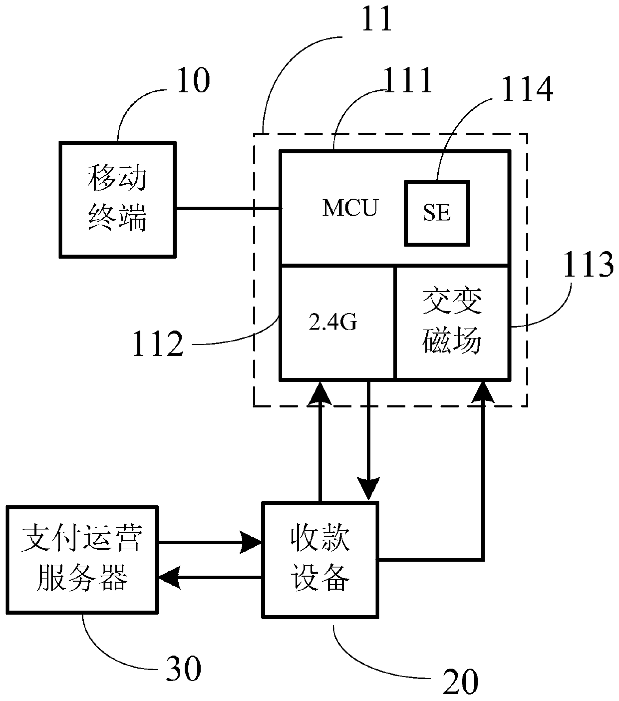
[0041] Such as figure 1 Shown is a schematic diagram of the architecture of a mobile payment system provided in this specification. The system may include a mobile terminal 10 and a collection device 20; wherein, the mobile terminal 10 has a Range Controlled Communication (RCC) module 11, The RCC module 11 may specifically include a Bluetooth Low Energy (BLE) communication module 111, a 2.4G communication module 112, an alternating magnetic field module 113, and a Microcontroller Unit (MCU) 114;
[0042] The alternating magnetic field module 113 is used to identify the device information and 2.4G communication link parameters of the payment collection device 20 that are transmitted by the payment collection device 20 through the alternating magnetic field that supports limited-area communication;
[0043] The 2.4G communication module 112 is configured to establish a 2.4G communication link with the payment collection device 20;
[0044] The Bluetooth communication module 111 is used to establish a Bluetooth communication link with the mobile terminal 10;
[0045] The micro-control unit 114 is configured to transfer the device information 20 to the payment application installed on the mobile terminal 10 based on the Bluetooth communication link; and pass the payment code generated by the payment application according to the device information The 2.4G communication link is sent to the payment collection device 20, so that the payment collection device 20 completes the payment transaction corresponding to the payment code through the anti-scan code payment link.
[0046] Such as figure 1 As shown, the system may also include a payment operation server 30 for receiving and processing a payment transaction request initiated by the payment collection device 20 after the payment code is scanned. Specifically, an anti-scan code payment link may be established between the payment collection device 20 and the payment operation server 30 for executing the payment transaction request of the payment collection device 20.
[0047] Wherein, the mobile terminal 10 may include mobile devices such as smart phones, smart watches, and smart bracelets.
[0048] Wherein, the name of the payment device 20 may be different in different scenarios. For example, in a shopping place, the payment device 20 may be a POS (Point of Sales) machine; on a bus, the payment device 20 may be Refers to the smart bus credit card machine; in the subway scenario, the payment device 20 can be a subway gate (also called a wing gate); in short, no matter what the scenario, as long as it is a machine or device used for payment, it can be called It is a collection device.
[0049] Wherein, the limited area communication is a technology that uses 2.4G (sometimes also called 2.45G) combined with an alternating magnetic field to realize data communication.
[0050] The difference between the RCC and the aforementioned NFC may at least include:
[0051] 1. Different communication frequency bands. The communication frequency band of NFC is 13.56MHz; and the frequency band of RCC is 2.4G. The 2.4G is a general term, and its communication frequency band is generally between 2.400GHz-2.4835GHz, and some also include 2.45GHZ.
[0052] 2. The communication distance is different. The communication distance of NFC is usually within 10 centimeters; while RCC can realize the control of multiple communication distance intervals within 10 centimeters in short distance, within 50 centimeters in medium distance, and about 10 meters in long distance.
[0053] 3. The communication bandwidth is different. NFC communication bandwidth is between 106K-848K; and RCC is between 1M-8M, which is 10 times that of NFC; therefore, the response time of RCC is much shorter than that of NFC.
[0054] It is worth mentioning that RCC can be applied to a mobile phone SIM (Subscriber Identification Module) card to make an RCC-SIM card, and the mobile terminal can have RCC communication capabilities after inserting the RCC-SIM card. Similarly, it can also be applied to an SD card (Secure Digital Memory Card) to make an RCC-SD card, and the mobile terminal can have RCC communication capabilities after inserting the RCC-SD card.
[0055] In an implementation manner: the foregoing limited-domain communication module may refer to an RCC-SUM card, that is, the mobile terminal is inserted with an RCC-SUM card, so that the mobile terminal can have RCC communication capabilities.
[0056] In another implementation manner: the aforementioned domain-limited communication module may refer to a hardware module with RCC function alone, and the hardware module may be integrated on the main board of the mobile terminal, so that the mobile terminal can have RCC communication capabilities.
[0057] Similarly, a collection device that wants to have RCC capabilities also needs to have an RCC module; of course, since the collection device does not need to have all the communication capabilities of a mobile terminal, it may not have a Bluetooth module.
[0058] In summary, the mobile device can implement RCC communication with the RCC-supporting payment collection device based on the RCC module, and the mobile device can finally transmit the payer to the payment collection device through the RCC communication method to realize payment. On the one hand, due to the high communication efficiency of RCC, the response time of each payment can be shortened; on the other hand, the user only needs to put the mobile terminal close to the collection device, and does not need to perform many operations like scan code payment; so this manual is used The provided embodiments can quickly complete mobile payments, greatly reduce the length of payment, and improve payment efficiency.
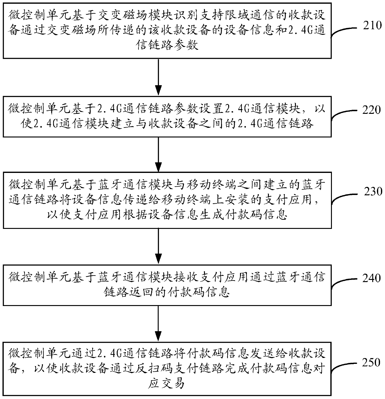
[0059] Please refer to figure 2 The flow chart of a mobile payment method provided in this specification is shown, the method is applied to a mobile terminal, the mobile terminal integrates a restricted area communication module, and the restricted area communication module includes a Bluetooth communication module, a 2.4G communication module, Alternating magnetic field module and micro control unit, the method includes:
[0060] Step 210: The micro-control unit identifies, based on the alternating magnetic field module, the device information and 2.4G communication link parameters of the payment collection device that are transferred by the payment collection device supporting limited-area communication through the alternating magnetic field.
[0061] Step 220: The micro control unit sets the 2.4G communication module based on the 2.4G communication link parameters, so that the 2.4G communication module establishes a 2.4G communication link with the payment device;
[0062] Step 230: The micro control unit transmits the device information to the payment application installed on the mobile terminal based on the Bluetooth communication link established between the Bluetooth communication module and the mobile terminal, so that the payment application Generate a payment code according to the device information;
[0063] Step 240: The micro-control unit receives the payment code returned by the payment application through the Bluetooth communication link based on the Bluetooth communication module;
[0064] Step 250: The micro control unit sends the payment code to the payment device via the 2.4G communication link, so that the payment device completes the payment code corresponding to the payment code via the anti-scan code payment link. Payment transaction.
[0065] As mentioned earlier, restricted area communication can refer to a technology that uses 2.4G (sometimes also called 2.45G) combined with an alternating magnetic field to achieve data communication.
[0066] The following describes a complete mobile payment transaction process.
[0067] When a user needs to make a mobile payment, he can bring his mobile terminal (the mobile terminal integrates an RCC module) close to a collection device that supports RCC transactions. Wherein, the payment collection device continuously sends its own device information and 2.4G communication link parameters through an alternating magnetic field. The device information may include the collection device number (usually the number is unique, and a number corresponds to a unique device) and/or the location of the collection device. The location can be the current city, and can be specifically located Latitude and longitude.
[0068] When the mobile terminal is close enough to the payment collection device, the MCU of the RCC module on the mobile terminal can identify the device information and 2.4G communication link parameters sent by the payment collection device based on the alternating magnetic field module.
[0069] At this time, on the one hand, the MCU can set the 2.4G communication module according to this 2.4G communication link parameter; because this 2.4G communication link parameter is the parameter for establishing the 2.4G communication link agreed by the collection device, so when the 2.4G communication After the module has also set the 2.4G communication link parameters, it can establish a 2.4G communication link with the collection device.
[0070] On the other hand, the MCU may establish a Bluetooth communication link between the Bluetooth communication module and the mobile terminal, and transfer the device information to the payment application installed on the mobile terminal, so that the payment application A payment code is generated according to the device information; and the MCU may receive the payment code returned by the payment application through the Bluetooth communication link based on the Bluetooth communication module. Wherein, the payment application generates a payment code according to the device information, which may specifically include:
[0071] Based on the payment code generation algorithm, the payment code is generated according to the device information, code factor and transaction timestamp. The transaction timestamp may generally refer to the current timestamp when the payment code is generated, and is provided by the payment application.
[0072] After the MCU receives the payment code, it can send the payment code to the payment device based on the 2.4G communication link established and maintained before, so that the payment device can complete the payment through the anti-scan code payment link. The payment transaction corresponding to the payment code.
[0073] The anti-scan code payment link is as follows figure 1 As shown, it is a link established between the collection device and the payment operation server for executing the collection transaction request of the collection device. After receiving the payment code, the payment device can scan the payment code to obtain the payer’s account information, add the amount to be collected and other information to assemble the payment request, and send the payment request based on the anti-scan code payment link To the payment operation server, the payment operation server completes the transaction according to the message in the payment request, for example, in the case of determining the payer’s account, the receiver’s account, and the payment amount, deduct the payment amount from the payer’s account Funds and inject the deducted funds into the recipient’s account.
[0074] The following examples are applicable to the application scenarios of mobile payment solutions in this manual.
[0075] Can be applied to public transportation scenarios:
[0076] The payer may include a public transportation ride code. Specifically: the bus code when taking the bus; the subway code when taking the subway; the light rail code when taking the light rail; the code when taking high-speed rail, high-speed rail and other trains.
[0077] It can also be applied to daily shopping scenarios:
[0078] For example, payment for shopping in stores, payment for unmanned vending machines (unmanned ticket vending machines, crane machines, food and beverage machines, self-service camera machines, etc.).
[0079] Please note that the above application scenarios are just a few examples and are not limited to the implementation of the above application scenarios; it should be understood that all mobile payment application scenarios can implement the mobile payment solutions provided in this manual.
[0080] In the mobile payment solution provided in this specification, the mobile device can implement RCC communication with the RCC-supporting payment collection device based on the RCC module, and the mobile device can finally transmit the payer to the payment collection device through RCC communication to realize payment. On the one hand, due to the high communication efficiency of RCC, the response time of each payment can be shortened; on the other hand, the user only needs to put the mobile terminal close to the collection device, and does not need to perform many operations like scan code payment; so this manual is used The provided embodiments can quickly complete mobile payments, greatly reduce the length of payment, and improve payment efficiency.
[0081] In the implementation process of the foregoing embodiment, the payment application needs to intervene to generate the payment code, so the payment application in the mobile terminal needs to be always turned on during the payment process. Under normal circumstances, payment application permissions can be set in the operating system of the mobile terminal, such as keeping the payment application running in the background when the screen is off, or the payment application self-starting, etc.; in this way, the user can implement RCC communication mobile when the screen is off Paid. However, in actual applications, users may not set payment application permissions; or some security software restricts payment applications from starting automatically, automatically closing payment applications running in the background, etc., which will cause mobile payments to be disabled when the mobile terminal is off. For this reason, this manual also provides another mobile payment solution to solve the problem of smooth mobile payment when the screen of the mobile terminal is off.
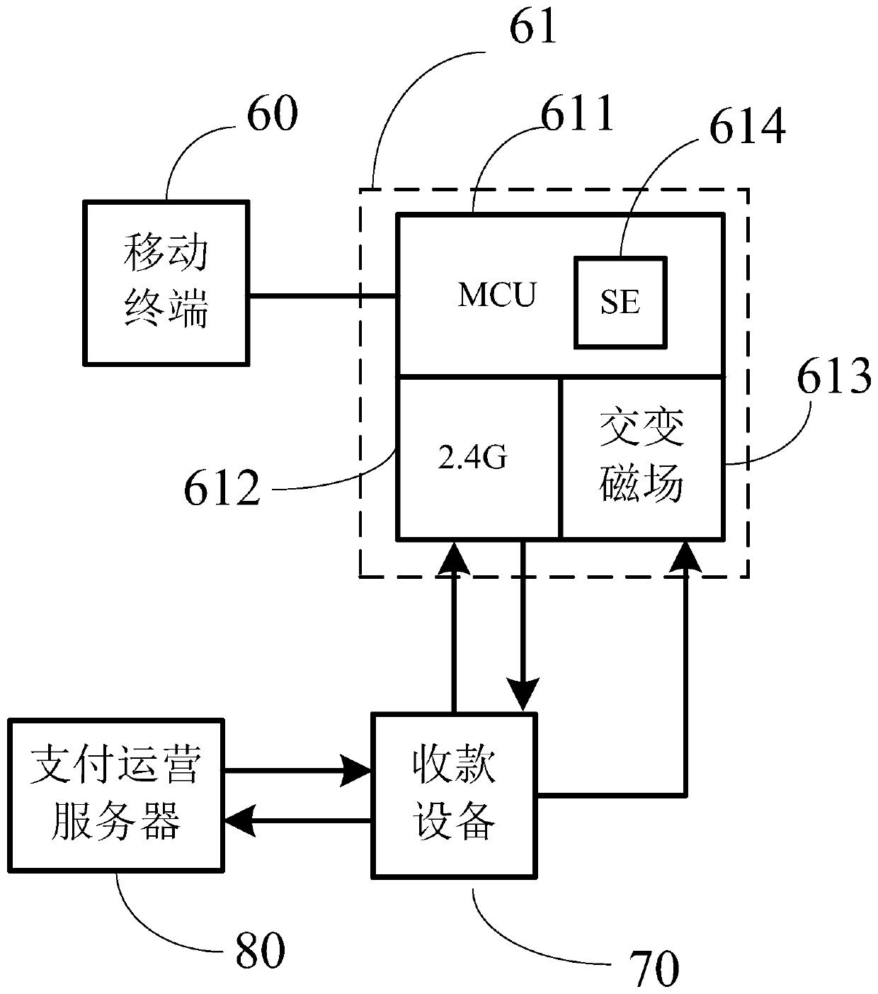
[0082] Such as image 3 Shown here is a schematic diagram of the architecture of a mobile payment system provided in this specification. The system includes a mobile terminal 60 and a collection device 70; wherein, the mobile terminal 60 has a restricted area communication module 61, and the restricted area communication module 61 Specifically, it includes a 2.4G communication module 612, an alternating magnetic field module 613, and a micro-control unit 611. The secure element (SE) 614 in the micro-control unit 611 stores a payment code generation algorithm and a code factor provided by the payment application;
[0083] The alternating magnetic field module 613 is used to identify the device information and 2.4G communication link parameters of the payment collection device 70 that are transmitted by the payment collection device 70 through the alternating magnetic field that supports limited-area communication;
[0084] The 2.4G communication module 612 is used to establish a 2.4G communication link with the payment collection device 70;
[0085] The micro control unit 611 is configured to receive the transaction timestamp sent by the payment collection device 70 through the 2.4G communication link; and based on the payment code generation algorithm in the security chip 614 according to the device information, the code factor and the transaction timestamp Generate payment code;
[0086] The micro control unit 611 is further configured to send the payment code to the payment device 70 through the 2.4G communication link, so that the payment device 70 completes the payment through the anti-scan code payment link The payment transaction corresponding to the code.
[0087] Such as image 3 As shown, the system may further include a payment operation server 80 for receiving and processing a payment transaction request initiated by the payment collection device 80 after the payment code is scanned. Specifically, an anti-scanning code payment link may be established between the collection device 70 and the payment operation server 80 for executing the collection transaction request of the collection device 80.
[0088] Wherein, the mobile terminal 60 may include mobile devices such as smart phones, smart watches, and smart bracelets.
[0089] Among them, the name of the payment device 70 may be different in different scenarios. For example, in a shopping place, the payment device 70 may be a POS machine; on a bus, the payment device 70 may be a smart phone. Bus credit card machine; in the subway scene, the collection device 70 can be a subway gate (also called a wing gate); in short, no matter what the scene, as long as it is a machine or device used for collection, it can be called a collection equipment.
[0090] The RCC technology in this embodiment is the same as the foregoing embodiment, and will not be repeated here.
[0091] In this embodiment, the mobile device can implement RCC communication with the RCC-capable receiving device based on the RCC module, and the mobile device can finally transmit the payer to the receiving device through RCC communication to realize payment. On the one hand, due to the high communication efficiency of RCC, the response time of each payment can be shortened; on the other hand, the user only needs to put the mobile terminal close to the collection device, and does not need to perform many operations like scan code payment; so this manual is used The provided embodiments can quickly complete mobile payments, greatly reduce the payment time, and improve payment efficiency; on the other hand, since the operation of the RCC module is not affected by the mobile terminal, as long as the mobile terminal is powered, the payment code can be generated through the security chip in the RCC module , So even when the mobile terminal screen is off, it can still realize the mobile payment of RCC communication.
[0092] Please refer to Figure 4 The flow chart of a mobile payment method provided in this specification is shown, the method is applied to a mobile terminal, the mobile terminal integrates a limited field communication module, and the limited field communication module includes a 2.4G communication module and an alternating magnetic field module A payment code generation module and a micro-control unit, wherein a security chip in the micro-control unit stores a payment code generation algorithm and a code factor provided by a payment application, and the method includes:
[0093] Step 310: The micro-control unit identifies, based on the alternating magnetic field module, the device information and 2.4G communication link parameters of the payment device that the payment device that supports limited-area communication transmits through the alternating magnetic field;
[0094] Step 320: The micro control unit sets the 2.4G communication module based on the 2.4G communication link parameters, so that the 2.4G communication module establishes a 2.4G communication link with the payment device;
[0095] Step 330: The micro control unit receives the transaction timestamp sent by the payment collection device based on the 2.4G communication link;
[0096] Step 340: The micro control unit generates a payment code based on the payment code generation algorithm in the security chip according to the device information, the code factor and the transaction timestamp;
[0097] Step 350: The micro-control unit sends the payment code to the payment device via the 2.4G communication link, so that the payment device completes the payment code corresponding to the payment code via the anti-scan code payment link Payment transaction.
[0098] As mentioned earlier, restricted area communication can refer to a technology that uses 2.4G (sometimes also called 2.45G) combined with an alternating magnetic field to achieve data communication.
[0099] The following is also described in conjunction with a complete mobile payment transaction process.
[0100] When a user needs to make a mobile payment, he can bring his mobile terminal (the mobile terminal integrates an RCC module) close to a collection device that supports RCC transactions. Wherein, the payment collection device continuously sends its own device information and 2.4G communication link parameters through an alternating magnetic field. The device information may include the collection device number (usually the number is unique, and a number corresponds to a unique device) and/or the location of the collection device. The location can be the current city, and can be specifically located Latitude and longitude.
[0101] When the mobile terminal is close enough to the payment collection device, the MCU of the RCC module on the mobile terminal can identify the device information and 2.4G communication link parameters sent by the payment collection device based on the alternating magnetic field module.
[0102] At this time, the MCU can set the 2.4G communication module according to this 2.4G communication link parameter; because this 2.4G communication link parameter is the parameter for establishing the 2.4G communication link agreed by the collection device, so when the 2.4G communication module is also set After the 2.4G communication link parameters are set up, a 2.4G communication link with the collection device can be established.
[0103] After the 2.4G communication link is established, the collection device may send a transaction time stamp based on the 2.4G communication link; the transaction time stamp may refer to the time stamp when the collection device sends it. Please pay attention to figure 2 The difference in the embodiment is that the transaction timestamp in this embodiment is provided by the collection device. The reason is that the payment application in this embodiment does not participate in the generation of the payment code, and the transaction timestamp is indispensable, so the payment collection device provides the transaction timestamp.
[0104] Then, after the MCU receives the transaction time stamp based on the 2.4G communication link, it can generate a payment code based on the device information, code factor, and transaction time stamp based on the payment code generation algorithm in the security chip.
[0105] It should be noted that the timeliness of the code factor is divided into permanent validity and long-term validity. Either way, it needs to be provided by the payment application installed in the mobile terminal, specifically:
[0106] The code factor is transmitted by the payment application installed in the mobile terminal through the Bluetooth communication link. To this end, the RCC module also needs to set up a Bluetooth communication module ( image 3 Not shown in); and the Bluetooth communication module can establish a Bluetooth communication link with the mobile terminal, and receive the code factor delivered by the payment application based on the Bluetooth communication link.
[0107] Among them, the code factor that is valid for a long time will eventually become invalid. For this type of code factor; whenever the payment application is opened, the payment application can pass the latest code factor to the SE in the RCC module through the Bluetooth communication link To update the code factor stored in SE.
[0108] After the SE generates the payment code, the MCU can send the payment code to the payment device based on the 2.4G communication link established and maintained before, so that the payment device can complete the payment through the anti-scan code payment link. The payment transaction corresponding to the payment code.
[0109] The anti-scan code payment link is as follows image 3 As shown, it is a link established between the collection device and the payment operation server for executing the collection transaction request of the collection device. After receiving the payment code, the payment device can scan the payment code to obtain the payer’s account information, add the amount to be collected and other information to assemble the payment request, and send the payment request based on the anti-scan code payment link To the payment operation server, the payment operation server completes the transaction according to the message in the payment request, for example, in the case of determining the payer’s account, the receiver’s account, and the payment amount, deduct the payment amount from the payer’s account Funds and inject the deducted funds into the recipient’s account.
[0110] The following examples are applicable to the application scenarios of mobile payment solutions in this manual.
[0111] Can be applied to public transportation scenarios:
[0112] The payer may include a public transportation ride code. Specifically: the bus code when taking the bus; the subway code when taking the subway; the light rail code when taking the light rail; the code when taking high-speed rail, high-speed rail and other trains.
[0113] It can also be applied to daily shopping scenarios:
[0114] For example, payment for shopping in stores, payment for unmanned vending machines (unmanned ticket vending machines, crane machines, food and beverage machines, self-service camera machines, etc.).
[0115] Please note that the above application scenarios are just a few examples and are not limited to the implementation of the above application scenarios; it should be understood that all mobile payment application scenarios can implement the mobile payment solutions provided in this manual.
[0116] In this embodiment, the mobile device can implement RCC communication with the RCC-capable receiving device based on the RCC module, and the mobile device can finally transmit the payer to the receiving device through RCC communication to realize payment. On the one hand, due to the high communication efficiency of RCC, the response time of each payment can be shortened; on the other hand, the user only needs to put the mobile terminal close to the collection device, and does not need to perform many operations like scan code payment; so this manual is used The provided embodiments can quickly complete mobile payments, greatly reduce the payment time, and improve payment efficiency; on the other hand, since the operation of the RCC module is not affected by the mobile terminal, as long as the mobile terminal is powered, the payment code can be generated through the security chip in the RCC module , So even when the mobile terminal screen is off, it can still realize the mobile payment of RCC communication.
[0117] With the aforementioned figure 2 Corresponding to the illustrated embodiment of the mobile payment method, this specification also provides an embodiment of a mobile payment device. The device embodiments can be implemented by software, or by hardware or a combination of software and hardware. Taking software implementation as an example, as a logical device, it is formed by reading the corresponding computer business program instructions in the non-volatile memory into the memory through the processor of the device where it is located. From the hardware level, such as Figure 5 Shown is a hardware structure diagram of the device where the mobile payment device is located in this manual, except Figure 5 In addition to the processor, network interface, memory, and non-volatile memory shown, the device in which the device is located in the embodiment usually depends on the actual function of the mobile payment, and may also include other hardware, which will not be repeated here.
[0118] See Image 6 , The module diagram of the mobile payment device provided by an embodiment of this specification, the device corresponds to figure 2 In the illustrated embodiment, the device is applied to a mobile terminal, the mobile terminal integrates a limited field communication module, and the limited field communication module includes a Bluetooth communication module, a 2.4G communication module, an alternating magnetic field module, and a micro-control unit. The device includes:
[0119] Recognition unit 410, the micro control unit recognizes, based on the alternating magnetic field module, the device information and 2.4G communication link parameters of the payment device that are transmitted by the payment device that supports limited area communication through the alternating magnetic field;
[0120] The establishment unit 420, the micro-control unit sets the 2.4G communication module based on the 2.4G communication link parameters, so that the 2.4G communication module establishes a 2.4G communication link with the payment device;
[0121] The transfer unit 430, the micro control unit transfers the device information to the payment application installed on the mobile terminal based on the Bluetooth communication link established between the Bluetooth communication module and the mobile terminal, so that the payment The application generates a payment code according to the device information;
[0122] The receiving unit 440, the micro control unit receives the payment code returned by the payment application through the Bluetooth communication link based on the Bluetooth communication module;
[0123] The sending unit 450, the micro-control unit sends the payment code to the collection device through the 2.4G communication link, so that the collection device completes the corresponding payment code through the anti-scan code payment link Payment transactions.
[0124] Optionally, the device information includes the location of the payment device and/or the number of the payment device.
[0125] Optionally, the location includes the city.
[0126] Optionally, the payment code includes a public transportation ride code.
[0127] Optionally, the public transportation includes at least one of a bus, a subway, a light rail, and a high-speed rail.
[0128] With the aforementioned Figure 4 Corresponding to the illustrated embodiment of the mobile payment method, this specification also provides an embodiment of a mobile payment device. The device embodiments can be implemented by software, or by hardware or a combination of software and hardware. Taking software implementation as an example, as a logical device, it is formed by reading the corresponding computer business program instructions in the non-volatile memory into the memory through the processor of the device where it is located. From the hardware level, such as Figure 7 Shown is a hardware structure diagram of the device where the mobile payment device is located in this manual, except Figure 7 In addition to the processor, network interface, memory, and non-volatile memory shown, the device in which the device is located in the embodiment usually depends on the actual function of the mobile payment, and may also include other hardware, which will not be repeated here.
[0129] See Figure 8 , The module diagram of the mobile payment device provided by an embodiment of this specification, the device corresponds to Figure 4 In the illustrated embodiment, the device is applied to a mobile terminal, the mobile terminal integrates a limited field communication module, and the limited field communication module includes a 2.4G communication module, an alternating magnetic field module, a payment code generation module, and a micro control unit. The security chip in the micro control unit stores the payment code generation algorithm and the code factor provided by the payment application, and the device includes:
[0130] Recognition unit 510, the micro control unit recognizes, based on the alternating magnetic field module, the device information and 2.4G communication link parameters of the payment device that are transferred by the payment device that supports limited area communication through the alternating magnetic field;
[0131] The establishment unit 520, the micro-control unit sets the 2.4G communication module based on the 2.4G communication link parameters, so that the 2.4G communication module establishes a 2.4G communication link with the payment device;
[0132] The receiving unit 530, the micro control unit receives the transaction timestamp sent by the payment collection device based on the 2.4G communication link;
[0133] A generating unit 540, the micro-control unit generates a payment code based on the payment code generation algorithm in the security chip according to the device information, the code factor and the transaction timestamp;
[0134] The sending unit 550, the micro control unit sends the payment code to the payment device via the 2.4G communication link, so that the payment device completes the payment code correspondence through the anti-scan code payment link Payment transactions.
[0135] Optionally, the code factor is transmitted by a payment application installed in the mobile terminal through a Bluetooth communication link.
[0136] Optionally, the device information includes the location of the payment device and/or the number of the payment device.
[0137] Optionally, the location includes the city.
[0138] Optionally, the payment code includes a public transportation ride code.
[0139] Optionally, the public transportation includes at least one of a bus, a subway, a light rail, and a high-speed rail.
[0140] The systems, devices, modules or units explained in the above embodiments may be implemented by computer chips or entities, or implemented by products with certain functions. A typical implementation device is a computer. The specific form of the computer can be a personal computer, a laptop computer, a cellular phone, a camera phone, a smart phone, a personal digital assistant, a media player, a navigation device, an email receiving and sending device, and a game control A console, a tablet computer, a wearable device, or a combination of any of these devices.
[0141] For the implementation process of the functions and roles of each unit in the above-mentioned device, please refer to the implementation process of the corresponding steps in the above-mentioned method for details, which will not be repeated here.
[0142] As for the device embodiment, since it basically corresponds to the method embodiment, the relevant part can refer to the part of the description of the method embodiment. The device embodiments described above are merely illustrative. The units described as separate components may or may not be physically separated, and the components displayed as units may or may not be physical units, that is, they may be located in One place, or it can be distributed to multiple network units. Some or all of the modules can be selected according to actual needs to achieve the purpose of the solution in this specification. Those of ordinary skill in the art can understand and implement it without creative work.
[0143] the above Image 6 Describes the internal functional modules and structural diagrams of the mobile payment device, and its substantial execution body can be an electronic device, including:
[0144] processor;
[0145] A memory for storing processor executable instructions;
[0146] Wherein, the processor is configured to:
[0147] The micro-control unit identifies, based on the alternating magnetic field module, the device information and 2.4G communication link parameters of the payment collection device that is transferred by the payment collection device that supports limited-area communication through the alternating magnetic field;
[0148] The micro control unit sets the 2.4G communication module based on the 2.4G communication link parameters, so that the 2.4G communication module establishes a 2.4G communication link with the payment device;
[0149] The micro-control unit transmits the device information to the payment application installed on the mobile terminal based on the Bluetooth communication link established between the Bluetooth communication module and the mobile terminal, so that the payment application is based on the Device information generates payment code;
[0150] The micro control unit receives the payment code returned by the payment application through the Bluetooth communication link based on the Bluetooth communication module;
[0151] The micro control unit sends the payment code to the payment device via the 2.4G communication link, so that the payment device completes the payment transaction corresponding to the payment code via the anti-scan code payment link.
[0152] Optionally, the device information includes the location of the payment device and/or the number of the payment device.
[0153] Optionally, the location includes the city.
[0154] Optionally, the payment code includes a public transportation ride code.
[0155] Optionally, the public transportation includes at least one of a bus, a subway, a light rail, and a high-speed rail.
[0156] the above Figure 8 Describes the internal functional modules and structural diagrams of the mobile payment device, and its substantial execution body can be an electronic device, including:
[0157] processor;
[0158] A memory for storing processor executable instructions;
[0159] Wherein, the processor is configured to:
[0160] The micro-control unit identifies, based on the alternating magnetic field module, the device information and 2.4G communication link parameters of the payment collection device that is transferred by the payment collection device that supports limited-area communication through the alternating magnetic field;
[0161] The micro control unit sets the 2.4G communication module based on the 2.4G communication link parameters, so that the 2.4G communication module establishes a 2.4G communication link with the payment device;
[0162] The micro control unit receives the transaction timestamp sent by the payment collection device based on the 2.4G communication link;
[0163] The micro control unit generates a payment code based on the payment code generation algorithm in the security chip according to the device information, the code factor and the transaction timestamp;
[0164] The micro control unit sends the payment code to the payment device via the 2.4G communication link, so that the payment device completes the payment transaction corresponding to the payment code via the anti-scan code payment link.
[0165] Optionally, the code factor is transmitted by a payment application installed in the mobile terminal through a Bluetooth communication link.
[0166] Optionally, the device information includes the location of the payment device and/or the number of the payment device.
[0167] Optionally, the location includes the city.
[0168] Optionally, the payment code includes a public transportation ride code.
[0169] Optionally, the public transportation includes at least one of a bus, a subway, a light rail, and a high-speed rail.
[0170] In the above embodiment of the electronic device, it should be understood that the processor may be a central processing unit (English: Central Processing Unit, CPU for short), or other general-purpose processors or digital signal processors (English: Digital Signal Processor). , Referred to as DSP), application specific integrated circuit (English: Application Specific Integrated Circuit, referred to as ASIC), etc. The general-purpose processor can be a microprocessor or the processor can also be any conventional processor, etc., and the aforementioned memory can be a read-only memory (English: read-only memory, abbreviation: ROM), random access memory (English : Random access memory, referred to as RAM), flash memory, hard disk or solid state hard disk. The steps of the method disclosed in the embodiments of the present invention may be directly embodied as being executed and completed by a hardware processor, or executed and completed by a combination of hardware and software modules in the processor.
[0171] The various embodiments in this specification are described in a progressive manner, and the same or similar parts between the various embodiments can be referred to each other, and each embodiment focuses on the differences from other embodiments. In particular, for the electronic device embodiment, since it is basically similar to the method embodiment, the description is relatively simple, and the relevant parts can be referred to the part of the description of the method embodiment.
[0172] Those skilled in the art will easily think of other embodiments of this specification after considering the specification and practicing the invention disclosed herein. This specification is intended to cover any variations, uses, or adaptive changes of this specification, which follow the general principles of this specification and include common knowledge or customary technical means in the technical field that are not disclosed in this specification . The description and the embodiments are only regarded as exemplary, and the true scope and spirit of the description are pointed out by the following claims.
[0173] It should be understood that this specification is not limited to the precise structure described above and shown in the accompanying drawings, and various modifications and changes can be made without departing from its scope. The scope of this specification is only limited by the appended claims.

PUM

no PUM

Description & Claims & Application Information

We can also present the details of the Description, Claims and Application information to help users get a comprehensive understanding of the technical details of the patent, such as background art, summary of invention, brief description of drawings, description of embodiments, and other original content. On the other hand, users can also determine the specific scope of protection of the technology through the list of claims; as well as understand the changes in the life cycle of the technology with the presentation of the patent timeline. Login to view more.

Similar technology patents

Flexible electroluminescent X-ray image memory display panel

InactiveCN106384737APatterns are clear and accurateshort response time
Owner:SHANGHAI KERUN PHOSPHOR TECH

Classification and recommendation of technical efficacy words

Why Eureka
Try Eureka