A pixel driving circuit, its driving method, and a display device

A pixel driving circuit and driving sub-circuit technology, which is applied to static indicators, instruments, etc., can solve the problems affecting the display quality of display devices, the difference in electrical parameters of driving thin film transistors, and the drift of electrical parameters, so as to avoid leakage current signal drift, Avoid the Kink effect and ensure the effect of uniformity

Active Publication Date: 2021-01-26
BOE TECH GRP CO LTD +1
View PDF5 Cites 0 Cited by
  • Summary
  • Abstract
  • Description
  • Claims
  • Application Information

AI Technical Summary

Problems solved by technology

[0003] The object of the present invention is to provide a pixel driving circuit, its driving method, and a display device, which are used to solve the problem that due to differences in the electrical parameters of the driving thin film transistors, and with the prolongation of the display time of the display device, some electrical parameters drift to different degrees , resulting in problems that affect the display quality of the display device

Method used


Image

  • A pixel driving circuit, its driving method, and a display device
  • A pixel driving circuit, its driving method, and a display device
  • A pixel driving circuit, its driving method, and a display device

Examples


Embodiment Construction

[0052] In order to further illustrate the pixel driving circuit, its driving method, and the display device provided by the embodiments of the present invention, a detailed description will be given below in conjunction with the accompanying drawings.

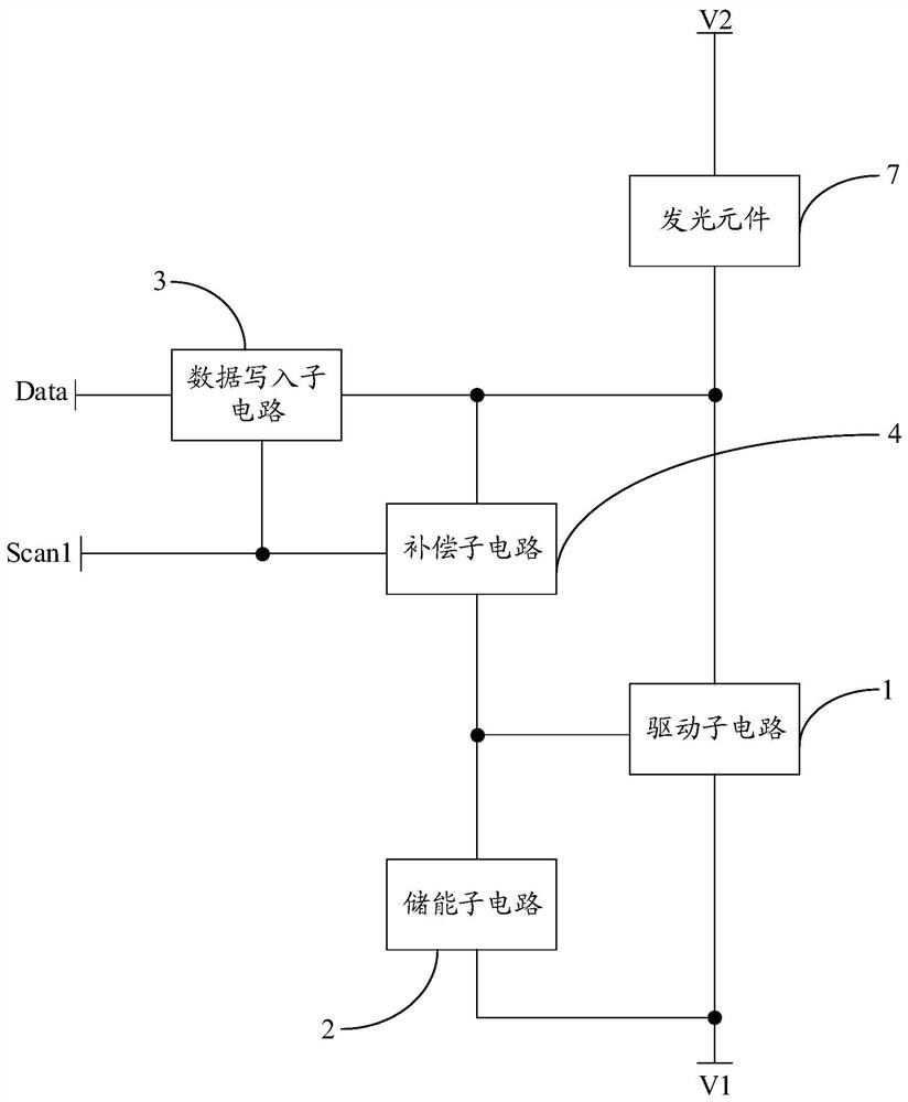
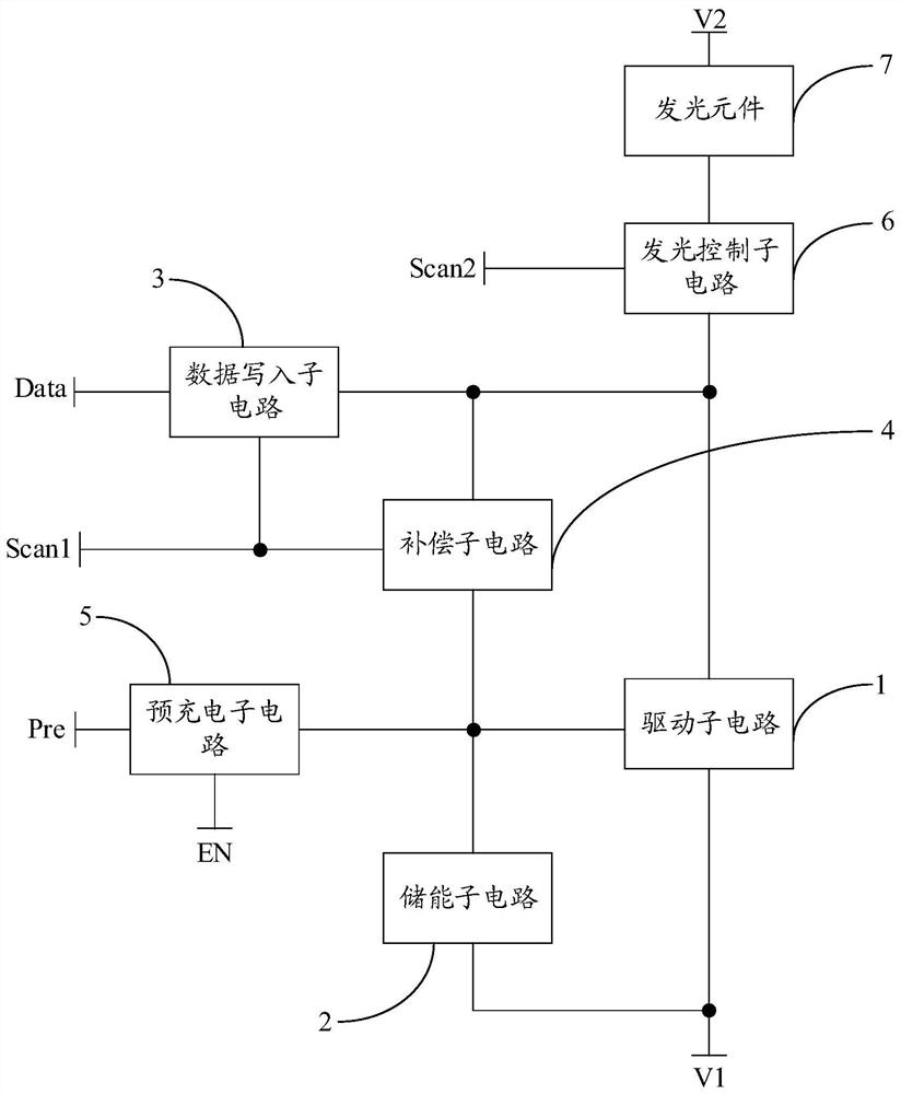
[0053] see figure 1 and Figure 4 As shown, the embodiment of the present invention provides a pixel driving circuit for driving the light-emitting element 7 to emit light. The pixel driving circuit includes: a driving sub-circuit 1, an energy storage sub-circuit 2, a data writing sub-circuit 3 and a compensation sub-circuit Circuit 4; wherein, the control end of the driving sub-circuit 1 is coupled to the first end of the energy storage sub-circuit 2, the first end of the driving sub-circuit 1 is coupled to the light-emitting element 7, and the second end of the driving sub-circuit 1 is coupled to the second end of the energy storage sub-circuit 2 A level signal input terminal V1 is coupled; the second terminal of the energy ...


PUM


Abstract

The invention discloses a pixel driving circuit, a driving method thereof, and a display device, and relates to the field of display technology. In order to solve the problem of differences in electrical parameters of driving thin film transistors and the prolongation of the display time of the display device, some electrical parameters occur to different degrees. The drift is a problem that affects the display quality of the display device. The pixel driving circuit includes: a driving subcircuit, an energy storage subcircuit, a data writing subcircuit and a compensation subcircuit; the data writing subcircuit is used to control the Conducting the coupling between the input terminal of the current data signal and the first terminal of the driving subcircuit; the compensation subcircuit is used to control the first terminal of the driving subcircuit to be turned on under the control of the first scan signal input terminal during the writing compensation period. Coupling between one terminal and the control terminal of the drive subcircuit. The pixel driving circuit provided by the present invention is used to drive the light emitting element to emit light.

Description

technical field [0001] The present invention relates to the field of display technology, in particular to a pixel driving circuit, a driving method thereof, and a display device. Background technique [0002] The OLED (Organic Light-Emitting Diode, Organic Light-Emitting Diode) display device has many advantages such as self-illumination, ultra-thin, fast response speed, high contrast ratio, and wide viewing angle, and is currently a display device that has attracted extensive attention. With the gradual increase in the size of OLED display devices, when manufacturing large-sized OLED display devices, due to the limitations of the manufacturing process and materials, there are differences in the electrical parameters such as the threshold voltage and mobility of the driving thin film transistors in each area of ​​the display device. , this difference will be transformed into current difference and brightness difference of the OLED display device, resulting in uneven display ...

Claims


Application Information

Patent Timeline
Patent Type & Authority Patents(China)
IPC IPC(8): G09G3/3233
CPCG09G3/3233
Inventor 陈芪飞鹿堃张晓哲周星柏玲徐迪徐东亮任亮亮卢姗卢景洲刘晓锋宋冠男马华平
Owner BOE TECH GRP CO LTD
Why Eureka
Try Eureka