Self-luminous imaging method and system

An imaging method and self-illumination technology, which is applied in the field of self-illumination imaging methods and systems, can solve problems such as poor imaging effects, achieve the effect of increasing flexibility and realizing the adjustment of luminous brightness and luminous color

Pending Publication Date: 2021-12-31
NINGBO GQY VIDEO &TELECOM
View PDF4 Cites 0 Cited by
  • Summary
  • Abstract
  • Description
  • Claims
  • Application Information

AI Technical Summary

Problems solved by technology

[0005] In order to solve the technical problem of poor imaging effect in space in the prior art, the present invention provides a self-illumination imaging method and system, and the specific technical solution is as follows:

Method used


Image

  • Self-luminous imaging method and system
  • Self-luminous imaging method and system
  • Self-luminous imaging method and system

Examples


Embodiment 1

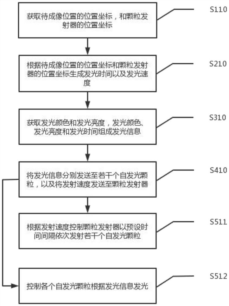
[0088] An embodiment of the present invention, such as figure 1 As shown, the present invention provides a self-luminous imaging method, including several self-luminous particles and particle emitters, including steps:

[0089] S110 Acquire the position coordinates of the position to be imaged and the position coordinates of the particle emitter.

[0090] Optionally, if the position to be imaged is located outside the emission track of the particle emitter, the particle emitter is adjusted according to the position coordinates of the position to be imaged so that the position to be imaged is located on the emission track of the particle emitter, and the particle emitter's Position coordinates.

[0091] S210 Generate a luminescence time and an emission speed according to the position coordinates of the position to be imaged and the position coordinates of the particle emitter.

[0092] Specifically, according to the position coordinates of the position to be imaged and the po...

Embodiment 2

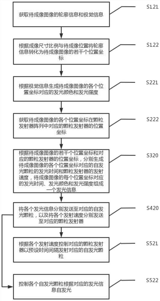
[0102] Another embodiment of the present invention, such as figure 2 As shown, the present invention also provides a self-illumination imaging method, including a plurality of particle emitters to form a particle emitter array, including steps:

[0103]S121 Acquire contour information and visual information of the image to be imaged.

[0104] Specifically, the visual information refers to the color information and brightness information of the outer contour of the image to be imaged.

[0105] S122 Convert the contour information into several position coordinates of the image to be imaged according to the imaging size ratio and the imaged location.

[0106] Specifically, each imaging point in the contour information of the image to be imaged is collected, and converted into each position coordinate of the image to be imaged according to each imaging point, the imaging size ratio, and the position to be imaged, and each imaging point corresponds to a position coordinate.

[0...

Embodiment 3

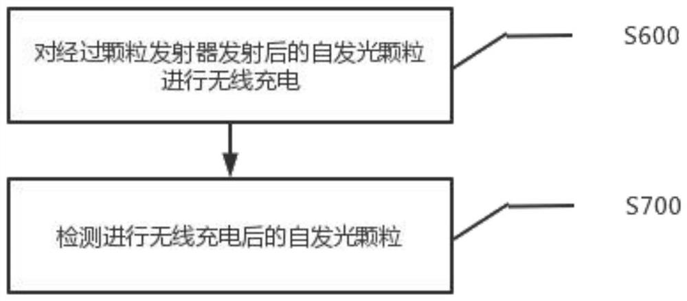
[0122] Based on Example 1, such as image 3 As shown, after controlling each self-luminous particle to emit light according to the light-emitting information in step S512, it also includes:

[0123] The S600 wirelessly charges the self-luminous particles emitted by the particle emitter.

[0124] Specifically, a wireless charging area composed of wireless charging components is set, and when the self-luminous particles are located in the wireless charging area, wireless charging is performed on the self-luminous particles.

[0125] The S700 detects self-luminous particles after wireless charging.

[0126] Specifically, when it is detected that the self-luminous particles are not fully charged, the self-luminous particles that are not fully charged are wirelessly charged or removed again, and when a failure of the self-luminous particles is detected, the faulty self-luminous particles are removed.

[0127] Further, when the same self-luminous particle is detected to be in a st...


PUM


Abstract

The invention discloses a self-luminous imaging method and system, wherein the method comprises a plurality of self-luminous particles and a particle emitter, and also comprises the steps: obtaining the position coordinates of a to-be-imaged position and the position coordinates of the particle emitter; generating light emitting time and emission speed according to the position coordinates of the position to be imaged and the position coordinates of the particle emitter; acquiring light emitting color and light emitting brightness, wherein the light emitting color, the light emitting brightness and the light emitting time form light emitting information; sending the light emitting information to a plurality of self-light-emitting particles, and sending the emission speed to the particle emitter; controlling the particle emitter to sequentially emit a plurality of self-luminous particles at a preset time interval according to the emission speed; and controlling each self-luminous particle to emit light according to the light emitting information. According to the invention, the effect that clear holographic images suspended in the air can be seen without wearing any additional equipment can be realized.

Description

technical field [0001] The invention relates to the field of imaging technology, in particular to a self-illumination imaging method and system. Background technique [0002] The current realization of the current holographic image is mainly through the image on a flat medium for reflecting the image, even if the principle of laser interference is used, a flat medium is required. Or use AR glasses to present 4D images in the human brain through binocular stereoscopic video and spatial position algorithms. [0003] In order to allow the viewer to see the holographic image suspended in the air without wearing any additional equipment, the method of air projection is generally used, and the principle of mirage is used to project the image on the single layer of water formed by the small water droplets formed by the liquefaction of water vapor. On the screen, due to the uneven vibration of molecules, a holographic image can be formed, but the effect of the holographic image is ...

Claims


Application Information

Patent Timeline
Patent Type & Authority Applications(China)
IPC IPC(8): G02B30/50
CPCG02B30/50
Inventor 王征
Owner NINGBO GQY VIDEO &TELECOM
Why Eureka
Try Eureka