
Waveguide filter and manufacturing method thereof

A waveguide filter and waveguide technology, applied in the fields of electromagnetic fields and microwaves, can solve the problems of difficulty in integrated processing and molding of filters, unsuppressed parasitic resonance, and narrow bandwidth of the non-parasitic stopband, so as to expand the bandwidth of the non-parasitic stopband , Improve the stop band rejection, no need for assembly and debugging

Active Publication Date: 2019-07-12
SHENZHEN UNIV
View PDF5 Cites 11 Cited by
  • Summary
  • Abstract
  • Description
  • Claims
  • Application Information

AI Technical Summary

Problems solved by technology

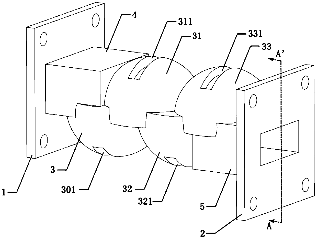
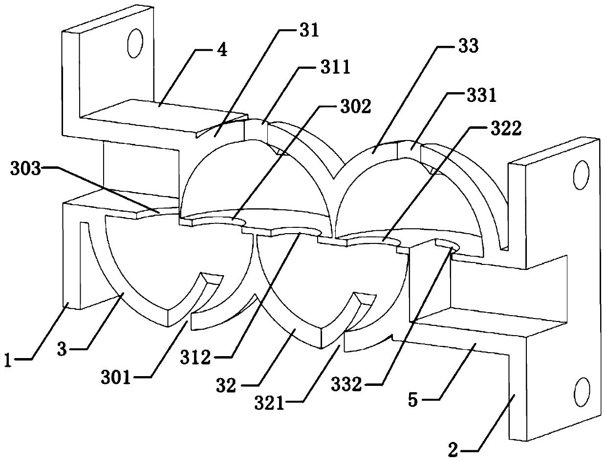
[0005] The main purpose of the present invention is to provide a waveguide filter and its manufacturing method, aiming to solve the problem that in the waveguide filter based on the spherical cavity resonator, the spurious resonance introduced by the high-order mode of the electromagnetic wave is not suppressed, and the bandwidth of the non-parasitic stopband is narrow , the technical problems of poor stop band suppression and difficulty in integrated processing and molding of filters

Method used


Image

  • Waveguide filter and manufacturing method thereof
  • Waveguide filter and manufacturing method thereof
  • Waveguide filter and manufacturing method thereof

Examples


Embodiment Construction

[0039] In order to make the purpose, features and advantages of the present invention more obvious and easy to understand, the technical solutions in the embodiments of the present invention will be clearly and completely described below in conjunction with the drawings in the embodiments of the present invention. It should be noted that the described embodiments are only some of the embodiments of the present invention, but not all of them. Based on the embodiments of the present invention, all other embodiments obtained by those skilled in the art without making creative efforts belong to the protection scope of the present invention.

[0040]In the description of the embodiments of the present invention, the given structural dimensions are preferred parameters. With reference to the embodiments of the present invention, the actual required performance can be further obtained by modifying the dimensional parameters of each component.

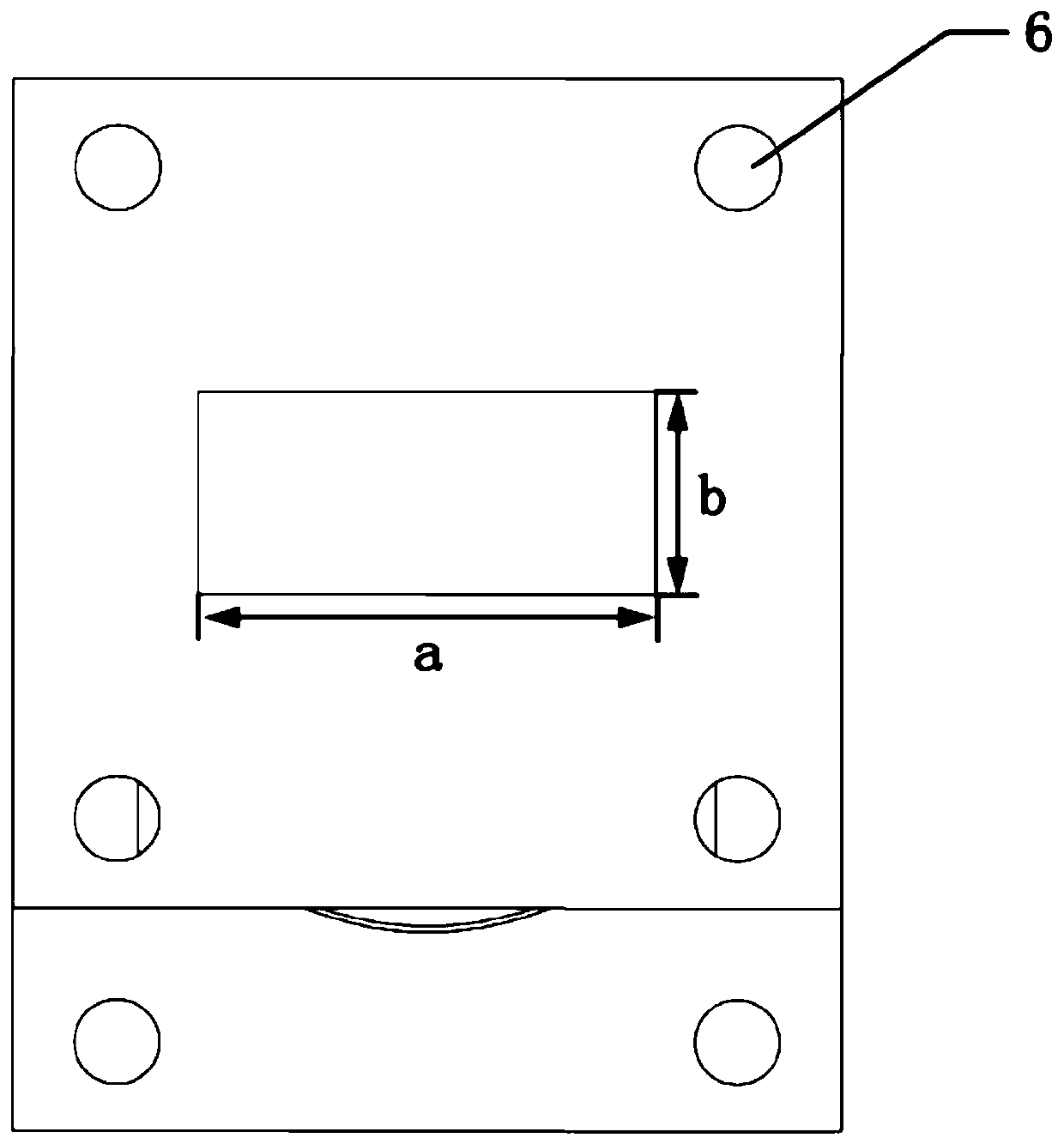
[0041] see figure 1 with figure 2 , ...


PUM


Abstract

The invention discloses a waveguide filter, and relates to the field of electromagnetic field and microwave technologies. The waveguide filter comprises a first waveguide flange plate, a second waveguide flange plate, a first waveguide, a second waveguide and four hemispherical resonators, wherein the cavity wall of each hemispherical resonator is provided with a through rectangular groove which is used for suppressing a high-order resonance mode of electromagnetic waves in the hemispherical resonator so as to expand the spurious-free stopband bandwidth of the waveguide filter. The invention further discloses a manufacturing method of the waveguide filter. The structure of the waveguide filter is integrally printed by a selective laser sintering 3-D printer through adopting a metal powdermaterial, does not need assembly and debugging while achieving accurate processing and effectively improves the manufacturing efficiency.

Description

technical field [0001] The invention relates to the technical field of electromagnetic fields and microwaves, in particular to a waveguide filter and a manufacturing method thereof. Background technique [0002] The air-filled metal cavity resonator is a basic frequency selective unit in microwave and millimeter wave passive circuits. It has the advantages of low radio frequency loss and large power capacity. It is used in filters, multiplexers, antennas and impedance matching networks. It is widely used in practice. Usually, these passive devices or circuits require metal cavity resonators with high unloaded quality factor to reduce radio frequency loss. [0003] Air-filled rectangular and cylindrical resonators are two commonly used high unloaded figure of merit cavity resonators, which are usually fabricated by conventional subtractive manufacturing processes such as computer numerical control milling. Thus a metal cavity resonator with a higher unloaded quality factor ...

Claims


Application Information

Patent Timeline
Patent Type & Authority Applications(China)
IPC IPC(8): H01P1/208H01P11/00
CPCH01P1/2082H01P11/007
Inventor 李津黄冠龙袁涛
Owner SHENZHEN UNIV
Learn More