Resonator waveguide filter

A waveguide filter and resonant cavity technology, which is applied in the field of filters, can solve the problems of difficult removal of support materials, easy damage of the coating, and poor quality of the metal coating, so as to achieve the effect of reducing the number and expanding the bandwidth of the non-parasitic stop band

Active Publication Date: 2022-02-18
SHENZHEN UNIV
View PDF6 Cites 0 Cited by
  • Summary
  • Abstract
  • Description
  • Claims
  • Application Information

AI Technical Summary

Problems solved by technology

For example, miniaturized stub-loaded resonator filters require a large number of tuning screws to compensate for the impact of loading stub processing errors on the RF performance of the filter; if such filters are made by 3-D printing processes, support materials need to be 3-D printed Aids in the formation of these nodular structures, while the support material in the cavity is difficult to remove after the device is formed
In addition, the discontinuity of the profile of these stubs leads to poor quality metallization on their edges, which is prone to damage
[0004] In the prior art, the resonant cavity in the filter can also be selectively slotted and matched with an appropriate interstage coupling structure to radiate the high-order mode of the resonant cavity without affecting the passband of the main mode, so as to suppress parasitic The purpose of resonating and expanding the filter's non-parasitic stopband bandwidth is that the electromagnetic radiation of the stopband on the bandpass filter will cause interference to the external circuit, which is not conducive to suppressing the external stopband interference signal

Method used


Image

  • Resonator waveguide filter
  • Resonator waveguide filter
  • Resonator waveguide filter

Examples


Embodiment Construction

[0035] In order to make the technical problems, technical solutions and beneficial effects to be solved by the present invention clearer, the present invention will be further described in detail below in conjunction with the accompanying drawings and embodiments. It should be understood that the specific embodiments described here are only used to explain the present invention, not to limit the present invention.

[0036] It should be noted that when an element is referred to as being “fixed” or “disposed on” another element, it may be directly on the other element or be indirectly on the other element. When an element is referred to as being "connected to" another element, it can be directly connected to the other element or indirectly connected to the other element.

[0037] It should be understood that the orientation or positional relationship indicated by the terms "length", "upper", "lower", "horizontal", "inner", "outer" and the like are based on the orientation or pos...


PUM


Abstract

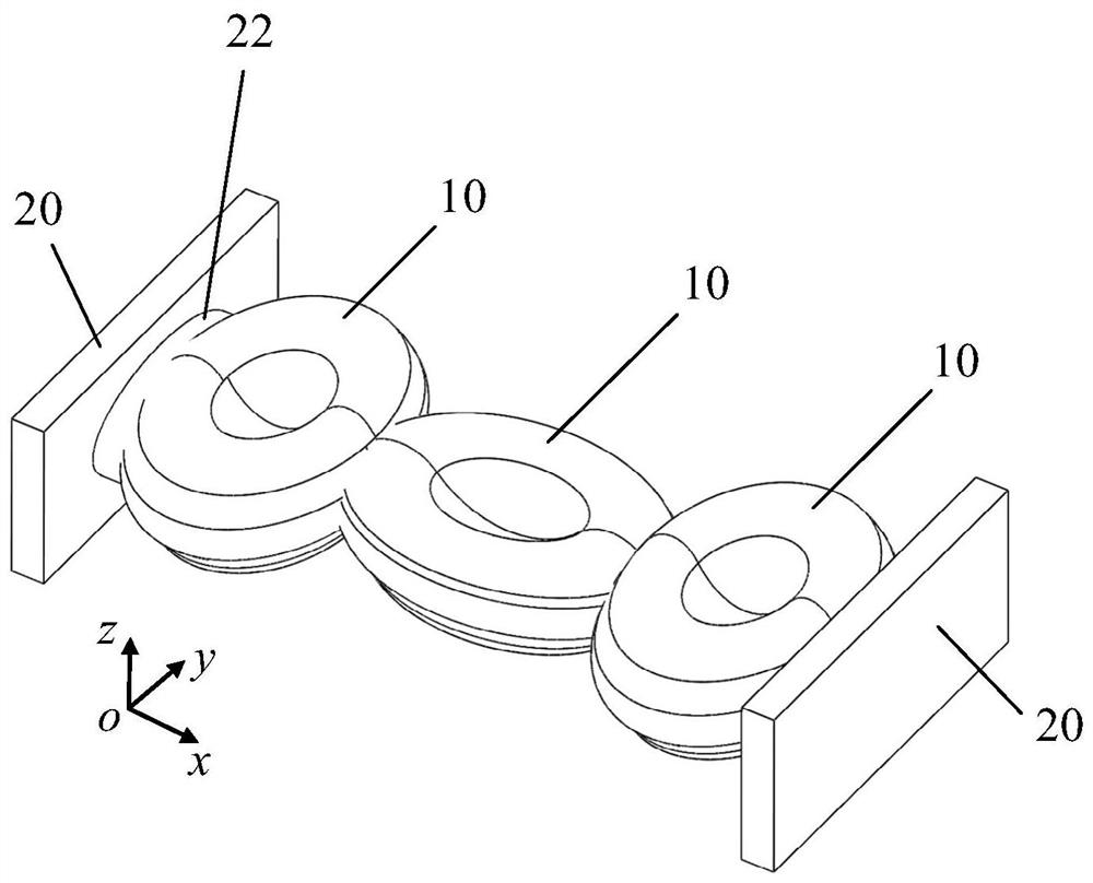
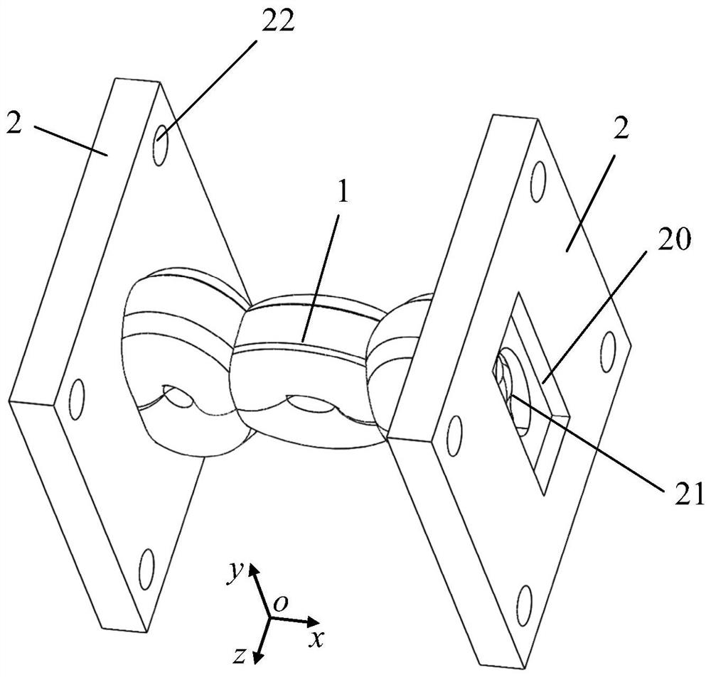
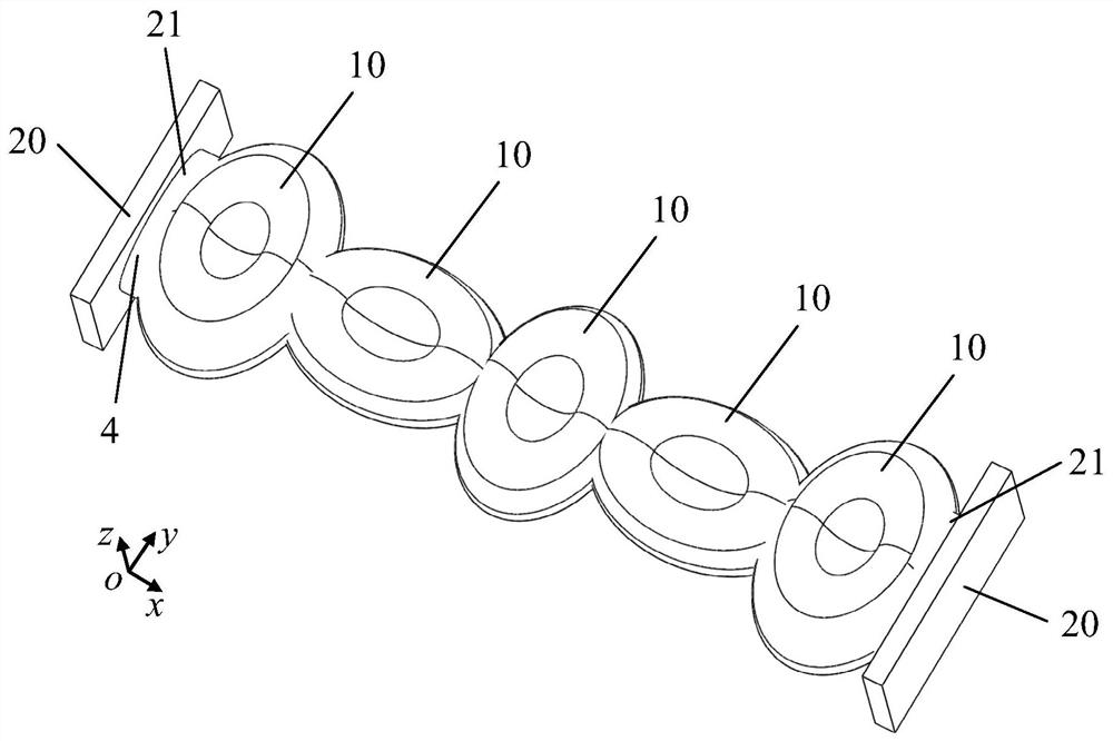
The invention provides a resonant cavity waveguide filter, which includes a metal shell and two waveguide flanges. The inside of the metal shell has a plurality of sequentially connected irregular resonant cavities. The resonant cavities have long axes perpendicular to each other and The short axis and the long axis of the adjacent resonant cavities are set vertically, and the long axes of the two resonant cavities located at both ends of the metal shell are set perpendicular to the length direction of the feeding rectangular waveguide. The resonant cavity constructed in the present invention has irregular metal boundary conditions, and on the premise of not significantly deteriorating the Q value of the fundamental mode of the resonant cavity, the number of high-order modes is reduced, and the frequency spectrum is far away from the fundamental mode; the resonance is pulled apart in the frequency spectrum The resonant frequency of the degenerate higher-order modes of the two polarization-orthogonal modes in the horizontal direction of the cavity, and by setting the continuous orthogonal scaling direction of the coupling resonator, the coupling coefficient of the two polarization-orthogonal higher-order modes is minimized , thereby suppressing these high-order modes to form a parasitic passband, which significantly improves the filter's non-parasitic stopband bandwidth and stopband rejection.

Description

technical field [0001] The invention belongs to the technical field of filters, and more specifically relates to a resonant cavity waveguide filter. Background technique [0002] Microwave filters for communication systems require their resonators to have a high quality factor (Q value) and radio frequency properties where the spurious resonant mode is far away from the main mode. The high-Q resonator can make the filter obtain smaller passband insertion loss under the same bandwidth. The far spurious resonant mode can make the upper stopband bandwidth of the bandpass filter wider and the suppression degree higher, so as to reduce the influence of harmonics and interference signals in the stopband. Traditional air-filled high-Q metal resonators, such as rectangular, cylindrical and spherical cavities, have regular and symmetrical boundary conditions, but because of the symmetry of the geometric structure, these resonators have a large number of degenerate high-order resonan...

Claims


Application Information

Patent Timeline
Patent Type & Authority Patents(China)
IPC IPC(8): H01P1/208
CPCH01P1/208H01P1/2082
Inventor 李津袁涛
Owner SHENZHEN UNIV
Why Eureka
Try Eureka