Spacer wire clamp rubber column packing tool

A technology of rubber columns and spacers, applied in the direction of overhead line/cable equipment, etc., can solve the problems of high purchase cost, high labor intensity, damaged rubber columns, etc., and achieve the effect of strong application value and low labor intensity

Pending Publication Date: 2019-07-12
中国电建集团河南电力器材有限公司
View PDF2 Cites 0 Cited by
  • Summary
  • Abstract
  • Description
  • Claims
  • Application Information

AI Technical Summary

Problems solved by technology

In the process of filling the rubber column in the spacer clamp, the general method is to put the cross shaft into the clamp body, and the worker uses a crowbar to penetrate the through hole of the cross shaft, tilt the cross shaft, and put it into the two sides on one side. Then turn the cross shaft in the opposite direction to fill the two rubber columns on the other side of the same side; then turn the opposite side of the clamp, and use the same method to tilt the cross shaft twice to fill the four rubber columns on the other side. , to complete the filling of the rubber column of the cable clamp. This method of manually embedding the rubber column consumes a lot of labor and the work efficiency is relatively low.
CN206060032U spacer rod clamp glue column assembly device and the announcement number is CN103500973B a spacer rotary wire clip eight-column damping column double-sided one-time filling tooling, both using a press and a mechanical mold (glue column positioning and guiding device), squeezed through the press Filling the rubber column by pressure reduces the labor intensity and improves the work efficiency, but there are disadvantages such as complicated equipment, high equipment purchase cost, easy damage to the rubber column during use, and the phenomenon that some rubber columns are crooked and cannot be filled.

Method used


Image

  • Spacer wire clamp rubber column packing tool
  • Spacer wire clamp rubber column packing tool
  • Spacer wire clamp rubber column packing tool

Examples


Embodiment 1

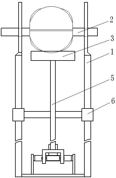
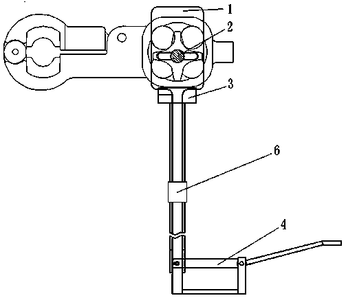
[0014] Such as figure 1 , figure 2 , image 3 As shown, the spacer rod wire clip rubber column filling tooling of the present invention includes two discrete support bodies 1, a straight rod 2, a pressing plate 3 and a pressing plate driving device; the straight rod 2 is movably inserted into the two support bodies 1 In the rod hole provided on the upper part; the pressing plate 3 is arranged between the two support bodies 1 below the straight rod 2, and the pressing plate 3 is connected to the pressing plate driving device and moves up and down under its action.

[0015] The pressing plate driving device is a pedal lever mechanism 4, the lever mechanism 4 is connected with the pressing plate connecting rod 5 through a rotating shaft, the pressing plate connecting rod 5 is fixedly connected with the pressing plate 3, and the pressing plate connecting rod 5 is fixedly connected with a guide sleeve arranged outside the bracket body 6. To ensure that the pressure plate 3 is no...

Embodiment 2

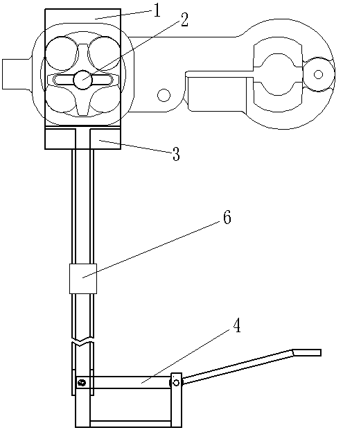
[0017] Such as Figure 4 As shown, the spacer rod wire clip rubber column filling tooling of the present invention includes two discrete support bodies 1, a straight rod 2, a pressing plate 3 and a pressing plate driving device; the straight rod 2 is movably inserted into the two support bodies 1 In the rod hole provided on the upper part; the pressing plate 3 is arranged between the two support bodies 1 below the straight rod 2, and the pressing plate 3 is connected to the pressing plate driving device and moves up and down under its action.

[0018] The platen driving device is a pneumatic telescopic rod 7 .


PUM


Abstract

The invention provides a spacer wire clamp rubber column packing tool. The tool comprises two separate bracket bodies, a straight rod, a pressing plate and a pressing plate driving device. The straight rod movably penetrates rod holes arranged at the upper portions of the two bracket bodies; the pressing plate is arranged between the two bracket bodies at the lower portion of the straight rod, andthe pressing plate is connected with the pressing plate driving device and moves up and down under the action of the pressing plate driving device. The spacer wire clamp rubber column packing tool issimple in structure, low in manufacturing cost, high in adaptability, convenient to operate, high in packing efficiency and free of damage to the rubber column.

Description

technical field [0001] The invention relates to the field of manufacturing equipment for electric power fittings, in particular to a spacer bar clamp rubber column filling tool. Background technique [0002] The damping spacer of the power fittings uses a damping structure composed of rubber columns and cross shafts at its movable joints to consume the vibration energy of the wires. When the line is affected by the wind during high-altitude operation, the line will vibrate in the air. Rubber columns and crosses The function of the shaft weakens and eliminates the vibration, thereby producing a damping effect on the vibration of the conductor. When assembling the damping spacer, it is necessary to put the cross shaft into the clamp body, fill the rubber column between the clamp and the cross shaft, and then connect the clamp arm through the cross shaft at the junction of the adjacent frames of the frame. In the process of filling the rubber column in the spacer clamp, the ge...

Claims


Application Information

Patent Timeline
IPC IPC(8): H02G1/02
CPCH02G1/02
Inventor 朱玉鹏乔庆文窦全峰周栓红
Owner 中国电建集团河南电力器材有限公司
Why Eureka
Try Eureka