Supercharge Your Innovation With Domain-Expert AI Agents!

Locking structure

A technology of lock and rotation adjustment, which is applied to home appliances, sanitary equipment, mechanical equipment, etc., can solve the problem of single structure and function of the lock, and achieve the effect of simple structure and convenient use

Pending Publication Date: 2019-07-16
广东顺德家好品金属制品有限公司
View PDF0 Cites 0 Cited by
  • Summary
  • Abstract
  • Description
  • Claims
  • Application Information

AI Technical Summary

Problems solved by technology

[0003] The present invention provides a locking structure to at least solve the problem of single function of the locking structure in the prior art

Method used


Image

  • Locking structure
  • Locking structure
  • Locking structure

Examples


Embodiment Construction

[0023] In order to enable those skilled in the art to better understand the solutions of the present invention, the following will clearly and completely describe the technical solutions in the embodiments of the present invention in conjunction with the drawings in the embodiments of the present invention. Obviously, the described embodiments are only It is an embodiment of a part of the present invention, but not all embodiments. Based on the embodiments of the present invention, all other embodiments obtained by persons of ordinary skill in the art without making creative efforts shall fall within the protection scope of the present invention.

[0024] It should be noted that the terms "first" and "second" in the description and claims of the present invention and the above drawings are used to distinguish similar objects, but not necessarily used to describe a specific sequence or sequence.

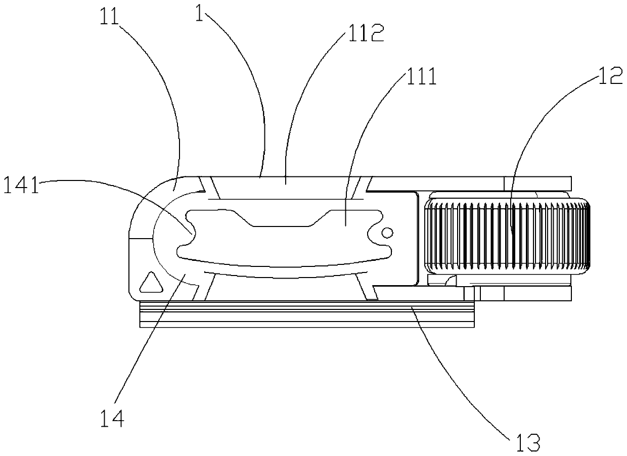
[0025] The embodiment of the present invention discloses a locking structure 1, s...


PUM


Abstract

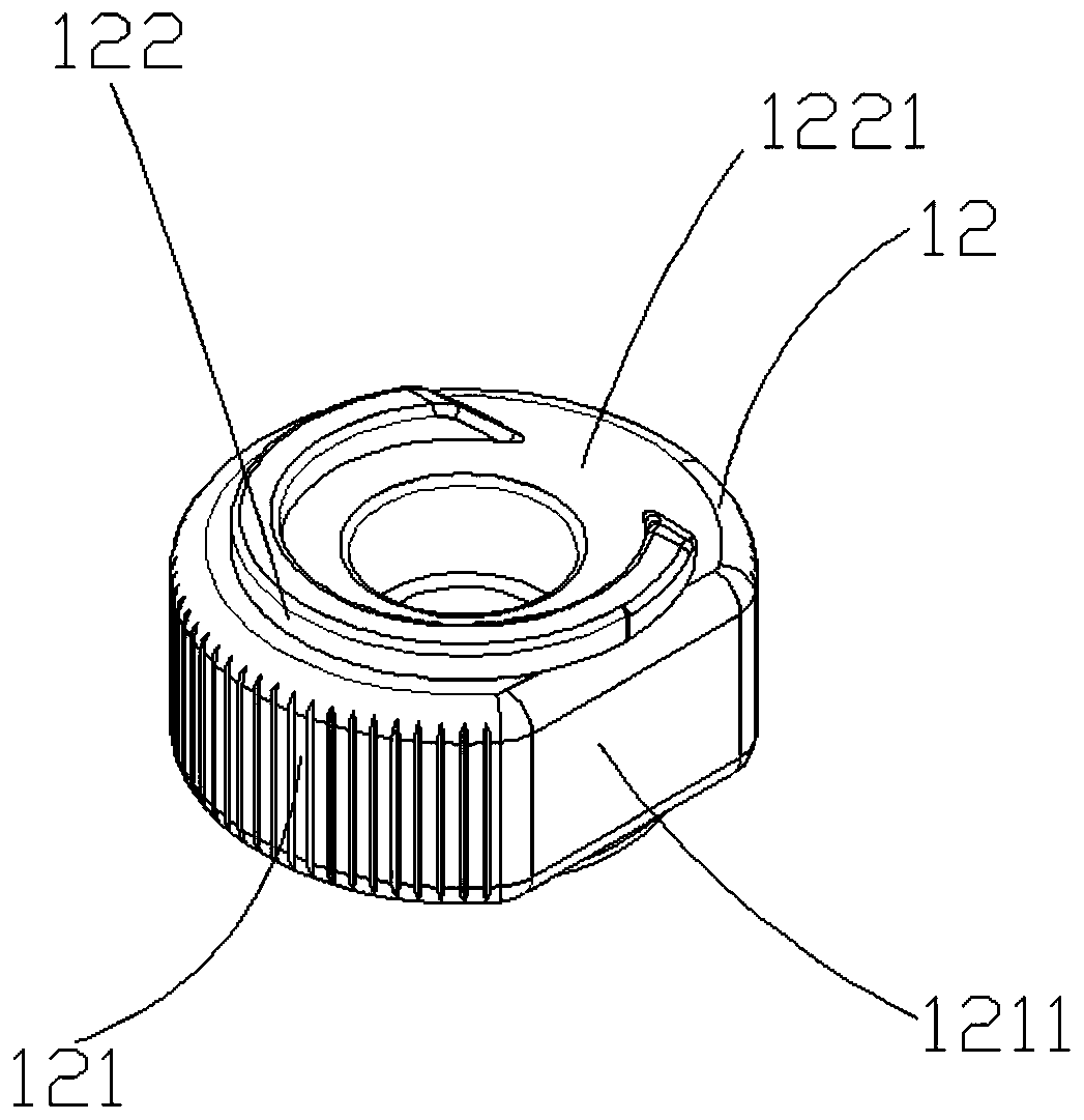
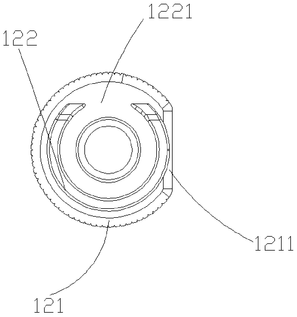
The invention provides a locking structure. The locking structure comprises a clamp piece, a rotating adjusting wheel, and a sliding groove, wherein a clamping groove opened on both ends is formed inthe clamp piece, the rotating adjusting wheel is rotatably mounted on the clamp piece, the wheel face of the rotating adjusting wheel is adjacent to one side of the clamping groove, the wheel face ofthe rotating adjusting wheel is of an annular structure composed of a circular arc surface and a plane, a ring outward flange is further arranged on one side of the rotating adjusting wheel, a concavepart is formed in the outward flange, the sliding groove is connected with the clamp piece, the sliding groove is located on the side, provided with the outward flange, of the rotating adjusting wheel, a pressable rod is arranged on the side, close to the outward flange, of the sliding groove, the one end of the pressable rod is fixed to the sliding groove, the other end of the pressable rod is located at the position of the outward flange, a bump structure is further arranged on the side, close to the outward flange, of the pressable rod, and the pressable rod is pressed against the outwardflange through the bump structure. The locking structure is simple in structure, and the clamping groove and the sliding groove can be adjusted by using the rotating adjusting wheel correspondingly.

Description

technical field [0001] The invention relates to a locking structure, in particular to a locking structure capable of bidirectional fixing. Background technique [0002] The existing storage racks are mainly fixed on the wall by means of steel nails, glue, etc., but they do not have a position adjustment function, resulting in poor applicability, and cannot be effectively adjusted according to the needs of customers. With the rise of housing prices, most people cannot buy large-area housing, and small-area housing and commercial housing have emerged and become popular. However, due to the small total area of ​​small-area housing and commercial housing, the use of space is cramped. The accommodating rack cannot meet the demands of consumers' diversity. The storage frame gradually develops into a combined and adjustable structure, but the lock structure used in the existing adjustable storage frame only has a one-way adjustment function, so when the storage frame needs to adju...

Claims


Application Information

Patent Timeline
IPC IPC(8): A47K5/00A47K10/12F16B1/00
CPCA47K5/00A47K10/12F16B1/00
Inventor 麦海荣闫栋
Owner 广东顺德家好品金属制品有限公司
Features
  • R&D
  • Intellectual Property
  • Life Sciences
  • Materials
  • Tech Scout
  • Unparalleled Data Quality
  • Higher Quality Content
  • 60% Fewer Hallucinations
Learn More