
Blanking die for low-stress blanking machine

A low-stress, mold-based technology, applied in the direction of non-rotational vibration suppression, etc., can solve problems such as the inability to adhere to the bar, wear of the bar, and small contact area

Inactive Publication Date: 2019-07-16
CHINA UNIV OF PETROLEUM (EAST CHINA)
View PDF7 Cites 3 Cited by
  • Summary
  • Abstract
  • Description
  • Claims
  • Application Information

AI Technical Summary

Problems solved by technology

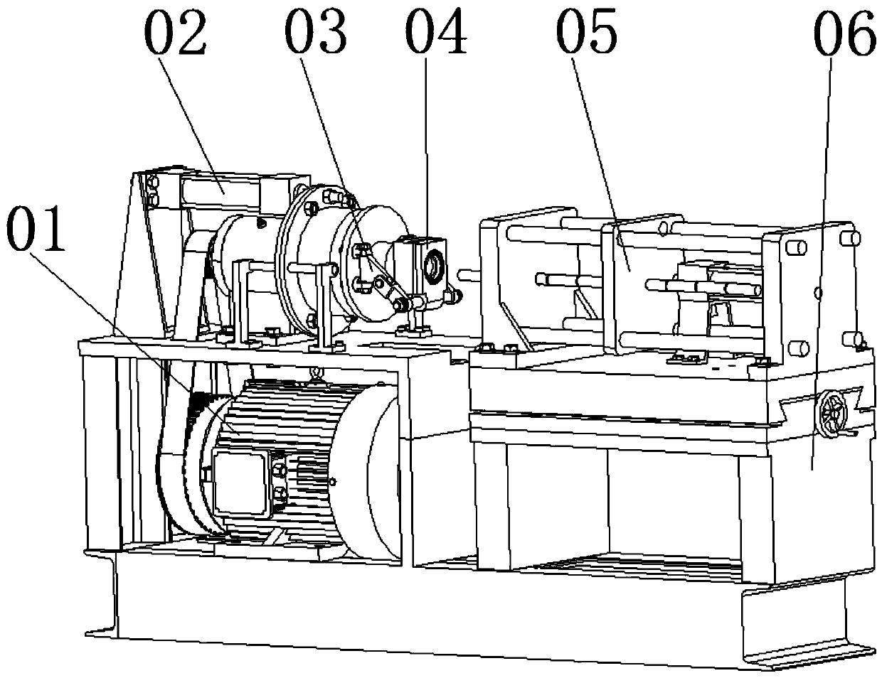
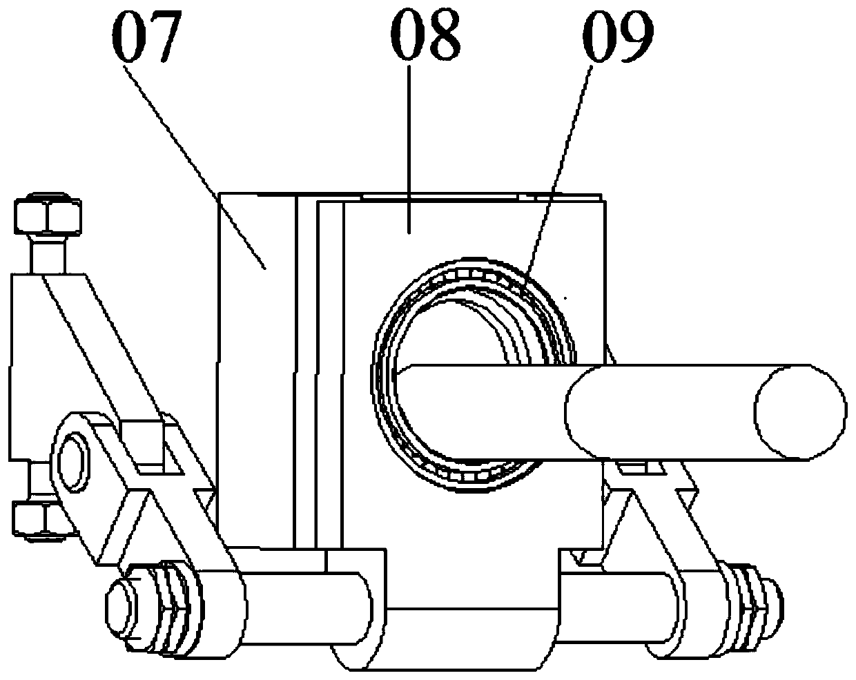
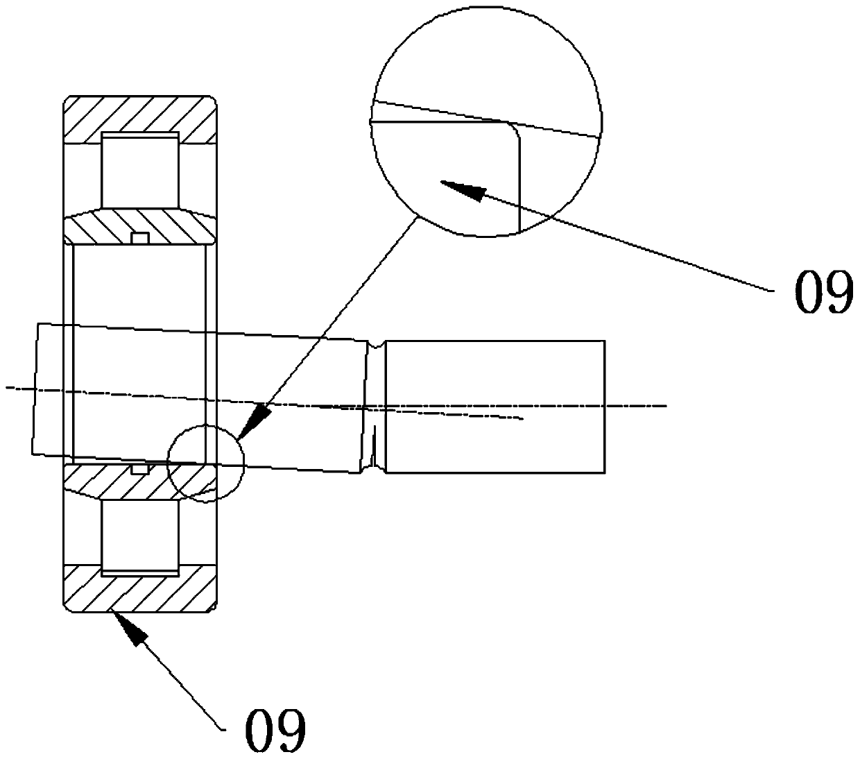
After a lot of analysis, the main reason is that during the blanking process, the bar is bent to a certain extent under the action of the blanking force, and a certain inclination angle appears, so that the bar cannot cling to the bearing 09 when the blanking mold 04 rotates. The inner ring makes the contact area between the bar and the inner ring of the bearing 09 too small, which causes the pressure on the contact surface to increase and the bar to wear on the contact surface seriously

Method used


Image

  • Blanking die for low-stress blanking machine
  • Blanking die for low-stress blanking machine
  • Blanking die for low-stress blanking machine

Examples


Embodiment Construction

[0021] In order to make the purpose, technical solutions and advantages of the present invention clearer, the present invention will be further described in detail below in conjunction with the accompanying drawings. Obviously, the described embodiments are only some of the embodiments of the present invention, rather than all of them. Based on the embodiments of the present invention, all other embodiments obtained by persons of ordinary skill in the art without making creative efforts belong to the protection scope of the present invention.

[0022] The following will combine Figure 4 ~ Figure 6 A blanking mold for a low-stress blanking machine according to an embodiment of the present invention will be described in detail.

[0023] refer to Figure 4 , Figure 5 and Figure 6 As shown, a blanking mold for a low-stress blanking machine provided by the embodiment of the present invention includes a lower slider 1, an upper slider 2, an inner hammer 3, a screw 4, a spring ...


PUM


Abstract

The invention discloses a blanking die for a low-stress blanking machine, and belongs to the technical field of intelligent manufacturing. An upper sliding block and a lower sliding block are splicedto form a hammer head containing cavity. An inner hammer head is arranged in the hammer head containing cavity. A bearing is fixed in an outer end inner cavity of the inner hammer head. The outer endof the inner hammer head is supported on an inner wall of the hammer head containing cavity by adopting a spring seat matched with a spring. The inner hammer head can do eccentric motion relative to the center line of the hammer head containing cavity in the hammer head containing cavity, namely, the inner hammer head can swing in the hammer head containing cavity according to needs, so that a rodcan completely make contact with the inner surface of the bearing when the rod is deflected, the friction contact surface between the rod and the bearing becomes large, the contact stress is reduced,and the friction abrasion of the contact surface of the rod is reduced. In addition, the outer end of the inner hammer head is supported on the inner wall of the hammer head containing cavity by adopting the spring seat matched with the spring, so that the damping effect can be realized, rapid centering can be realized during blanking next time, and the blanking process is more stable and reliable.

Description

technical field [0001] The invention relates to the technical field of intelligent manufacturing, in particular to a blanking mold for a low-stress blanking machine. Background technique [0002] Low-stress blanking is to apply crack technology to bar blanking. First, a circumferential crack is artificially prefabricated on the surface of the bar, and then a certain external force is applied to the bar with a circumferential surface crack, so that it can be cut at a low stress. Dynamic separation in the form of stress brittle fracture. Low-stress bending fracture blanking is recognized as the most promising precision blanking method in the future. It makes full use of the notch effect and bending effect of the circumferential V-shaped groove to achieve brittle fracture of materials at low stress levels and obtain geometry-free Distortion, vertical flat fracture, blank without chamfering. At present, scholars have conducted some research on low-stress bending blanking techn...

Claims


Application Information

Patent Timeline
IPC IPC(8): B21D28/14B21D28/04F16F15/04
CPCB21D28/04B21D28/14F16F15/04
Inventor 张立军张德潇韩琳李增辉金永山张军伟房绍伟
Owner CHINA UNIV OF PETROLEUM (EAST CHINA)
Learn More