Bending device of joint flexible turnout

A technology of deflection device and turnout, which is applied to roads, tracks, buildings, etc., can solve the problems of difficult installation and adjustment, difficult to ensure accuracy, and unfavorable maintenance, and achieve the effect of improving service life, improving accuracy and improving service life.

Active Publication Date: 2013-10-02
CHINA RAILWAY BAOJI BRIDGE GRP
View PDF5 Cites 14 Cited by
  • Summary
  • Abstract
  • Description
  • Claims
  • Application Information

AI Technical Summary

Problems solved by technology

At present, the existing deflection device has the following characteristics: first, the deflection curve of the turnout adopts the form of a circular curve, but the impact is large when the vehicle enters and exits this part of the line; The length of the contact line is reduced, which is prone to early wear; the third is that the guide surface and the support of the stable surface need to be lubricated, which is not conducive to maintenance; the fourth is that the cam is manufactured as a whole, which is difficult to manufacture and the accuracy is not easy to guarantee; the swing arm uses Welded structure, difficult to install and adjust on site

Method used


Image

  • Bending device of joint flexible turnout
  • Bending device of joint flexible turnout
  • Bending device of joint flexible turnout

Examples


Embodiment 1

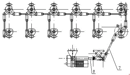
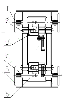
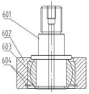
[0020] Embodiment 1: with reference to attached Figure 1-Figure 6-1 . A joint flexible turnout deflection device, including a guide panel, a stable panel, a mounting support, a cam support shaft, an axial cam, a double plug connecting rod, a roller assembly, a connecting rod pair, an electric push rod, and a deflection device The driving form of the serial connection of cam rods is used to realize the synchronous bending of the guide surface and the stable surface. The guide panel 1 and the stabilizer panel 5 are connected to the two ends of the double-fork pull rod 4 through hinged holes, and the double-fork pull rod 4 is connected to the driven assembly. Connected, the driven assembly is connected with the cylindrical cam mechanism, and the upper two adjacent cylindrical cam mechanisms and the upper and lower corresponding two cylindrical cam mechanisms 3 are connected through connecting rods. When the electric push rod 8 starts to push and pull; the pull rod drives The gu...

Embodiment 2

[0028] Embodiment 2: with reference to attached Figure 7 . A turnout line shape of a joint-flexible turnout device, including the fixed end of the turnout, the position of the lateral line of the movable end, and the linear position of the movable end. The transition curve is between the fixed end 501 of the turnout and the arc curve, and the arc curve and the movable end Between the end side line positions 502 is a gentle curve. Number 503 is the linear position of the movable end. Namely: Japan and Chuandong shipyard turnout adopted a single circular curve linear design. During use, there will be hard point transitions at the joints in the line; at the same time, due to the influence of beam width, there will be about 3mm of misaligned teeth on the guide surface and stable surface of the open end. The line shape of the turnout designed in this application takes into account the influence of the concrete beams at both ends, and the deflection line adopts a combination of ...


PUM


Abstract

The invention relates to a bending device of a special rail transfer joint flexible turnout for straddle type monorail traffic line. The bending device comprises guide panels, stabilization panels, mount supports, cam support shafts, axial cams, double-plug connecting rods, roller assemblies, a connecting rod pair and an electric push rod, and adopts a cam and pull rod series connection driving form to realize synchronous bending of a guide surface and a stabilization surface; the guide panels and the stabilization panels are connected with the two ends of the double-fork-head pull rods by reamed holes; the double-fork-head pull rods are connected with driven components; the driven components are contacted and connected with cylindrical cam mechanisms; the above two adjacent cylindrical cam mechanisms and the two vertically corresponding cylindrical cam mechanisms are connected by connecting rods; when the electric push rod starts to push and pull, the pull rod drives the guide panels to move transversely and synchronously, and therefore, the transverse bending of the guide panels is accomplished.

Description

technical field [0001] The invention relates to a joint-flexible turnout flexure device used in a straddle-type monorail traffic line, which belongs to the field of light rail line supporting equipment manufacturing. Background technique [0002] Joint-flexible turnout is a special track switching device used in straddle-type monorail transit lines. Currently, joint-flexible turnouts are produced by Hitachi Corporation in Japan and Chuandong Shipyard in China, and their products are used on the Chongqing Light Rail Line. The working principle of the turnout is: the articulated turnout is composed of multi-section beams. After the articulated turnout switches, the longitudinal direction of the turnout beam is in the shape of a broken line. The guiding surface and the stable surface of the articulated turnout are both planes. A large impact will occur when reaching the corner of the turnout beam joint, so the maximum allowable passing speed of the vehicle is 15Km / h, which can...

Claims


Application Information

Patent Timeline
Patent Type & Authority Applications(China)
IPC IPC(8): E01B7/14
Inventor 吉敏廷牛均宽都武仵叔强
Owner CHINA RAILWAY BAOJI BRIDGE GRP
Why Eureka
Try Eureka