Plant control system
A technology of equipment control and equipment, applied in the direction of program control, electrical control, mechanical equipment, etc., can solve problems such as excessive response deterioration, control instability, etc.
- Summary
- Abstract
- Description
- Claims
- Application Information
AI Technical Summary
Problems solved by technology
Method used
Image
Examples
no. 1 approach
[0083] First, refer to Figure 1 to Figure 8 A first embodiment of the present invention will be described.
[0084]
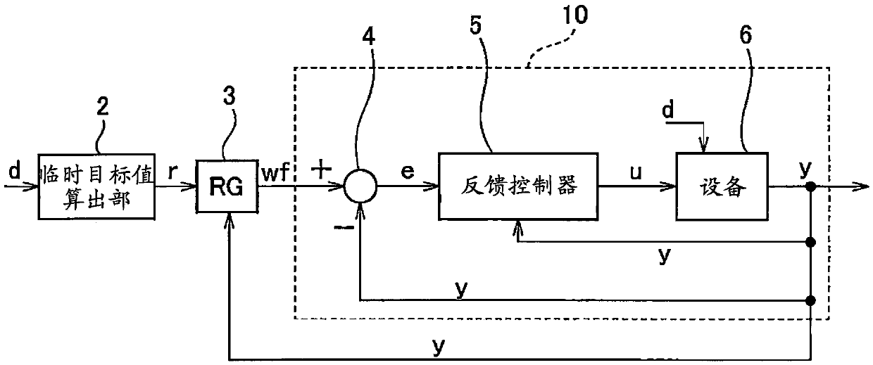
[0085] figure 1 It is a diagram showing the target value follow-up control structure of the facility control device according to the first embodiment. The facility control device includes a provisional target value calculation unit 2 , a reference regulator (RG) 3 , a comparison unit 4 , and a feedback controller 5 . For example, a microcomputer such as an electronic control unit (ECU) functions as an equipment control device.
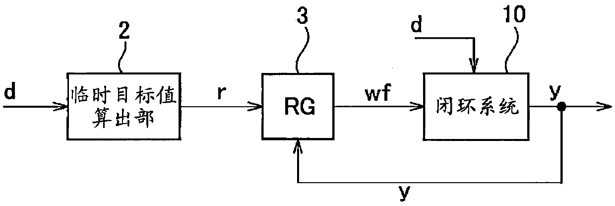
[0086] exist figure 1 A portion enclosed by a dotted line in , functions as a closed-loop system 10 that performs feedback control so that the control output y approaches the target value wf. After the closed-loop system 10 is designed, by figure 1 The target value tracking control structure of is obtained by equivalent deformation figure 2 The structure of the feedforward control. In addition, although a plurality of stat...
no. 2 approach
[0143] The configuration and control of the device control device in the second embodiment are basically the same as those of the device control device in the first embodiment except for the points described below. Therefore, the second embodiment of the present invention will be described below focusing on the parts different from the first embodiment.
[0144] In the second embodiment, the reference regulator 3 will correct the initial value w of the target value w 0 Set to r-0.5R r . r is the temporary target value, R r is the value of the partial differential of the objective function when the corrected target value w is the temporary target value r. R r It is obtained by substituting r into w on the right side of the above formula (16).
[0145] Figure 9 and Figure 10 It is a diagram for explaining the update method of the correction target value in the second embodiment using a graph showing the partial differential of the objective function. exist Figure 9 a...
no. 3 approach
[0177] The configuration and control of the device control device in the third embodiment are basically the same as those of the device control device in the first embodiment except for the points described below. Therefore, the third embodiment of the present invention will be described below focusing on the points different from the first embodiment.
[0178] In the third embodiment, the reference regulator 3 will correct the initial value w of the target value w 0 Set to r-0.5R r and a predetermined value between r. r is the temporary target value, R r is the value of the partial differential of the objective function when the corrected target value w is the temporary target value r. R r It is obtained by substituting r into w on the right side of the above formula (16).
[0179] Figure 15 ~ Figure 18 It is a diagram for explaining the update method of the correction target value in the third embodiment using a graph showing the partial differential of the objective ...
PUM
 Abstract
Description
Claims
Application Information
 - R&D
- Intellectual Property
- Life Sciences
- Materials
- Tech Scout
- Unparalleled Data Quality
- Higher Quality Content
- 60% Fewer Hallucinations
Browse by: Latest US Patents, China's latest patents, Technical Efficacy Thesaurus, Application Domain, Technology Topic, Popular Technical Reports.
© 2025 PatSnap. All rights reserved.Legal|Privacy policy|Modern Slavery Act Transparency Statement|Sitemap|About US| Contact US: help@patsnap.com


