A FAN and a combination structure of a fan wheel and a rotating shaft

A technology combining structure and shaft, applied to parts of pumping devices for elastic fluids, non-variable pumps, pump devices, etc., can solve problems affecting the service life of fans, wear or damage of plastic hubs, operating noise, etc.

Inactive Publication Date: 2019-07-16
SUNONWEALTH ELECTRIC MACHINE IND
View PDF9 Cites 0 Cited by
  • Summary
  • Abstract
  • Description
  • Claims
  • Application Information

AI Technical Summary

Problems solved by technology

[0003] However, the existing fan directly combines its plastic hub with a metal shaft. Due to the large difference in strength between the two materials, it often occurs that the plastic hub is worn or damaged when it contacts the shaft, which not only affects the use of the fan. life, and it is easy to cause noise when the fan wheel is in operation
In addition, the existing fan is only screwed to the rotating s

Method used


Image

  • A FAN and a combination structure of a fan wheel and a rotating shaft
  • A FAN and a combination structure of a fan wheel and a rotating shaft
  • A FAN and a combination structure of a fan wheel and a rotating shaft

Examples


Embodiment Construction

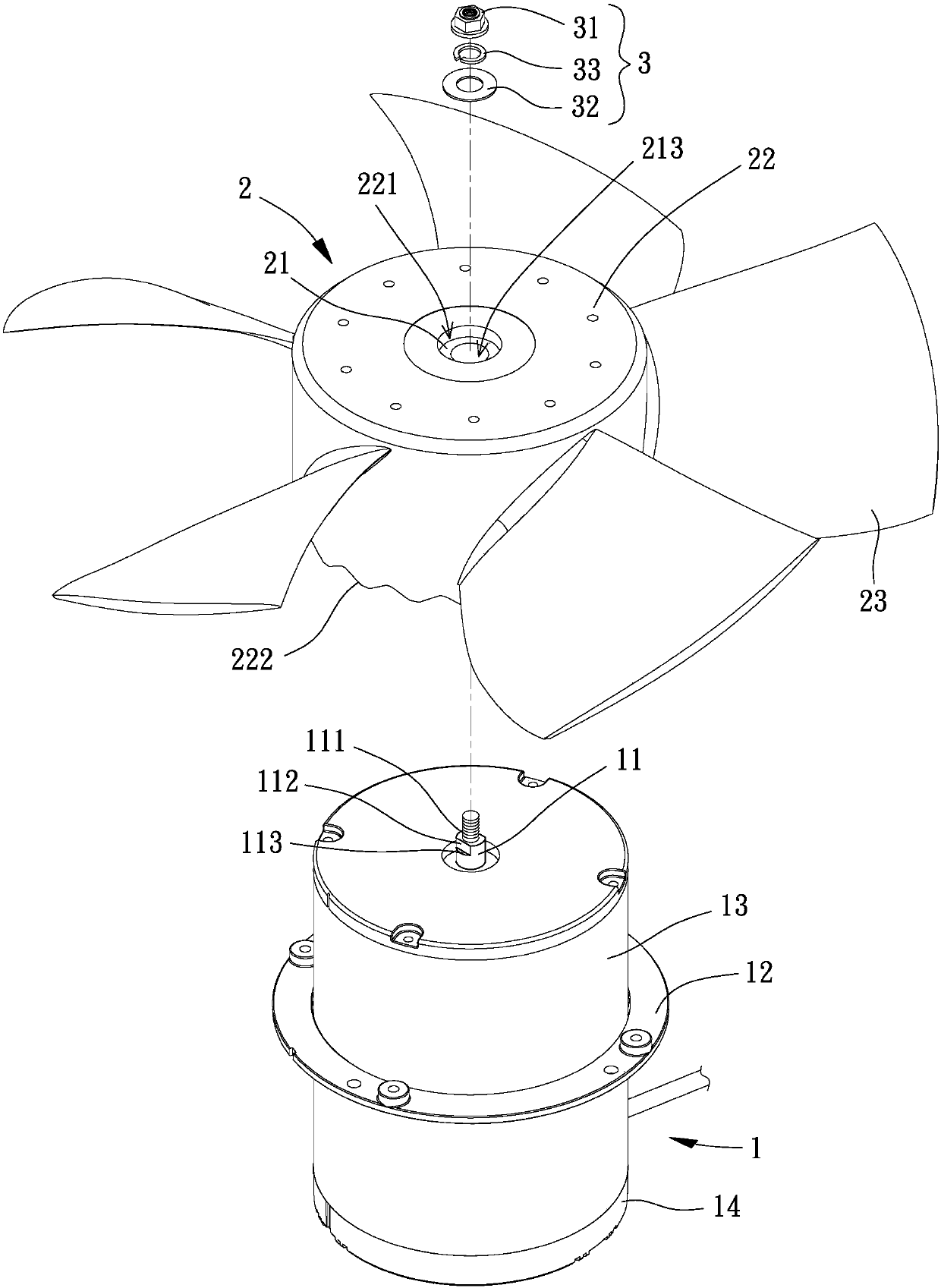
[0052] In order to make the above-mentioned and other objects, features and advantages of the present invention more comprehensible, the preferred embodiments of the present invention are listed below, together with the accompanying drawings, as follows:

[0053]Directionality or its approximate terms described below in the present invention, such as "front", "rear", "upper (top)", "lower (bottom)", "inner", "outer", "side", etc., are mainly With reference to the directions of the drawings, each direction or its approximate terms are only used to help explain and understand the various embodiments of the present invention, and are not intended to limit the present invention.

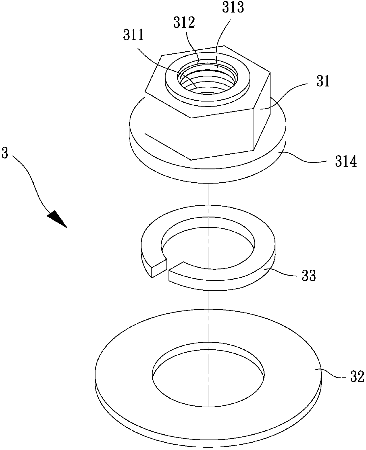
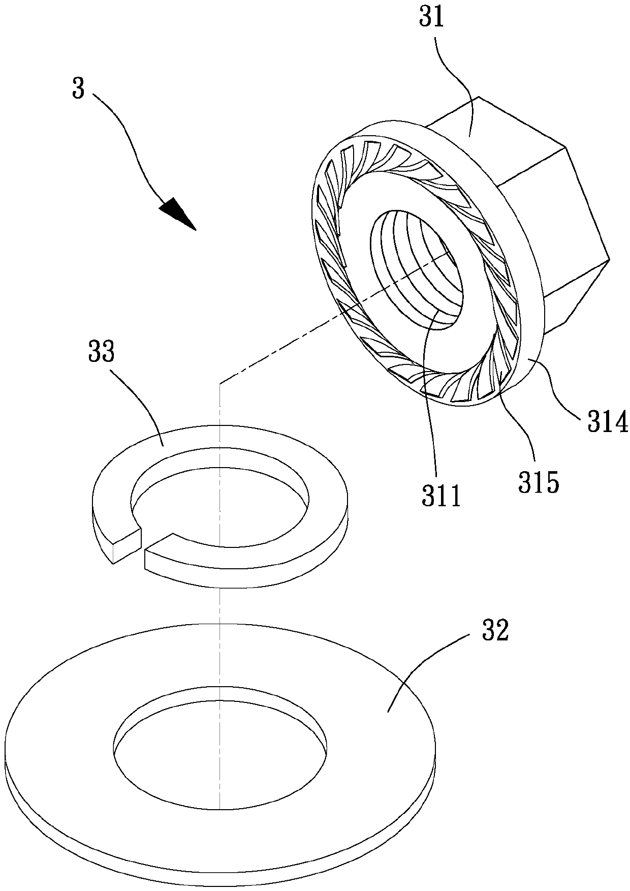
[0054] Please refer to figure 1 , which is an embodiment of the fan of the present invention, the fan generally includes a driving source 1 , a fan wheel 2 and a locking component 3 , the fan wheel 2 and the locking component 3 are combined with the driving source 1 .

[0055] The present invention does...


PUM


Abstract

The utility model relates to a fan and a combination structure of a fan wheel and a rotating shaft, which is used for solving the problem that the combination of the fan wheel and the rotating shaft of the fan is not stable in prior art. The fan of the present invention comprises: a driving source having a rotating shaft, wherein one end of the rotating shaft is provided with an external thread portion; and a fan wheel having a metal shaft seat and a hub, wherein the hub is coupled to the metal shaft seat and the metal shaft seat is coupled to the rotating shaft; and a locking assembly havinga fastener, wherein the inner circumference of the fastener is provided with an internal thread portion and a ring groove. The fastener has a The anti-slip ring that is fastened to the ring groove; the internal thread portion of the fastener is screwed to the external thread portion of the rotating shaft; and the anti-slip ring of the fastener is coupled to the external thread portion of the rotating shaft.

Description

technical field [0001] The invention relates to a combination structure of a fan and a fan wheel and a rotating shaft, in particular to a fan and a combination structure of a fan wheel and a rotating shaft capable of stably combining the fan wheel to the rotating shaft. Background technique [0002] The existing fan has a driving source and a fan wheel. When assembling, a plastic hub center of the fan wheel is inserted into a rotating shaft of the driving source to position, and then a nut is screwed to the rotating shaft and pressed against the rotating shaft. The plastic hub prevents the fan wheel from coming out of the rotating shaft during rotation. Several embodiments similar to the existing fans have been disclosed in patent cases such as Taiwan Publication No. I565879 and No. M500396. [0003] However, the existing fan directly combines its plastic hub with a metal shaft. Due to the large difference in strength between the two materials, it often occurs that the plas...

Claims


Application Information

Patent Timeline
IPC IPC(8): F04D25/08F04D29/34F04D29/32F04D29/66
CPCF04D25/08F04D29/325F04D29/34F04D29/663
Inventor 洪银树蔡期琮黄立仲
Owner SUNONWEALTH ELECTRIC MACHINE IND
Why Eureka
Try Eureka