Check valve and pump including check valve

a check valve and pump technology, applied in the field of check valves, can solve the problems of inconvenience of replacing the o ring, the sealing property of the o ring can be degraded, etc., and achieve the effects of low cost, simple structure, and pressure applied

Inactive Publication Date: 2005-08-11
COLUMBIA PEAK VENTURES LLC
View PDF7 Cites 53 Cited by
  • Summary
  • Abstract
  • Description
  • Claims
  • Application Information

AI Technical Summary

Benefits of technology

[0092] The pump includes the check valve as described above and thus has advantages in that it is small, has a simple structure, can be manufactured at low cost, allows the working fluid to flow smoothly, and is durable. Particularly, the advantages described above are noticeable in a small pump wherein the inertance of the outlet flow passage is larger than that of the inlet flow pass, and the pressure applied to the valve seat is large. The check value of the present invention is particularly effective for a small pump of a diaphragm type, etc., and the pump can be used for a cooling device of an electronic machine such as a projector, a water jet knife, a fluid actuator, a power source of a piston of a microhydraulic press, etc. It should be noted, however, that the present invention is not limited to the above uses.

Problems solved by technology

The sealing property of the O ring can be degraded with the use of the O ring for a long term and the inconvenience of the need for replacing the O ring at regular time intervals is involved.

Method used


Image

  • Check valve and pump including check valve
  • Check valve and pump including check valve
  • Check valve and pump including check valve

Examples


first embodiment

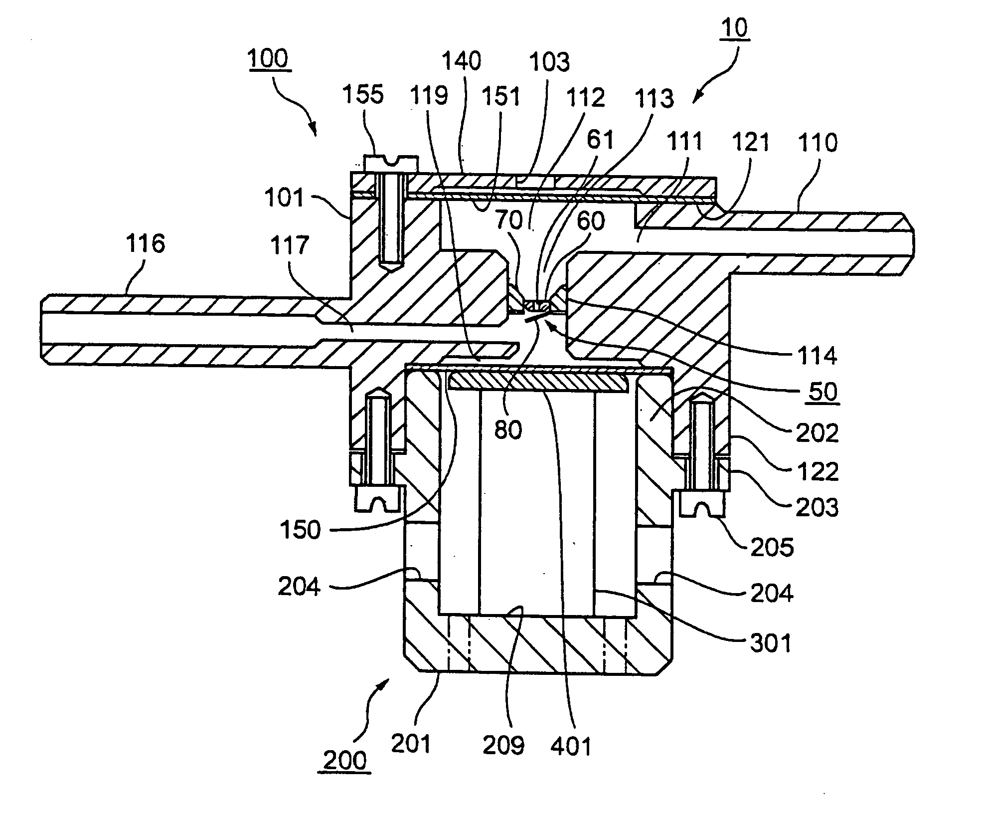
[0136]FIG. 1 is a longitudinal sectional view of the pump in which the check valve of the first embodiment is placed. In FIG. 1, the pump 10 includes a pump chamber unit 100 and an actuator unit 200.

[0137] The pump chamber unit 100 is made up of a pump chamber body 101 including an inlet flow pass 111 into which a working fluid is made to flow in and an outlet flow pass 117 from which the working fluid is made flow out, a diaphragm 150, and an elastic film 151 that may be used as pulsating flow absorption means for preventing a pulsating flow of the working fluid.

[0138] The pump chamber body 101 has an outside shape roughly like a cylinder in plan view. An inlet connection pipe 110 formed with the inlet flow pass 111 projects from one side of the pump chamber body 101, and the inlet flow pass 111 communicates with an elastic wall chamber 112. The tip of the inlet flow pass 111 is connected to external piping of a tube, etc., (not shown) for supplying the working fluid. On the oppos...

second embodiment

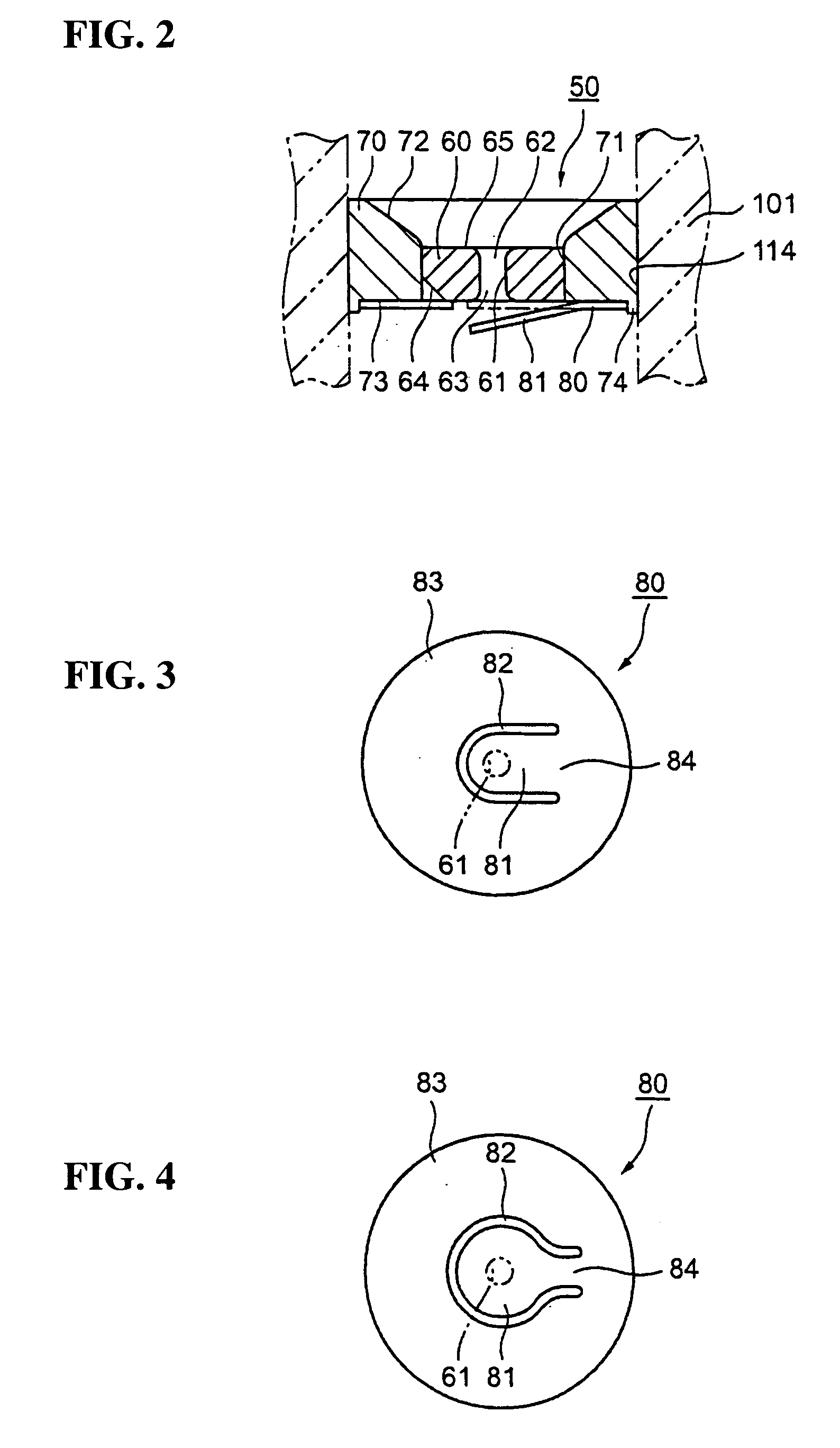
[0198] Therefore, in the second embodiment, the projection 74 of the valve seat frame 70 is crimped fully or partially, whereby the fixing part 83 of the valve body 80 is fixed to the valve seat frame 70. As such, the valve body 80 can be fixed in a small space reliably. The outer peripheral part of the fixing part 83 of the valve body 80 is fixed, whereby the valve body 80 can be fixed without deforming an opening-closing part 81 or a support part 84 (see FIG. 3) of the valve body 80.

[0199] The valve body 80 is simply placed in the projection 74 of the valve seat frame 70, whereby the position in the plane direction is regulated, so that the opening-closing part 81 can hermetically seal a communication hole 61 for the working fluid of the valve seat 60 reliably without using any special jig. FIG. 12 is a sectional view showing a check valve 50 of the third embodiment of the invention. In the third embodiment, the fixing structures of the valve bodies 80 to the valve seat frames 70 ...

third embodiment

[0202] Therefore, in the third embodiment, the valve body 80 is fixed as the fixing part 83 provided on the periphery is sandwiched between the valve seat frame 70 and the fixing member 90 so that the valve body 80 can be fixed without producing an internal stress. Thus, the valve body 80 can be fixed without deforming the support part 84 or the opening-closing part 81.


PUM


Abstract

A check valve includes a tubular valve seat frame, a valve seat that is fixedly secured to the inside of the valve seat frame and has a communication hole through which a working fluid flows, and a valve body that is on the working fluid outflow side of the valve seat for opening and closing the valve seat. The valve seat frame, the valve seat, and the valve body are put into one unit so that the check valve has a simple structure and a good assembly property, and can be manufactured at low cost. The check valve is included, whereby a small, durable, and high-performance pump can be provided.

Description

FIELD OF THE INVENTION [0001] The present invention relates to a check valve that can be built in a pump as a unit of a valve seat, a valve body, and a valve sheet frame and a pump including the check valve. DESCRIPTION OF THE BACKGROUND ART [0002] Hitherto, a pump for allowing a working fluid to flow has included a check valve as a resistance element in a fluid flow pass. Particularly, there are check valves adopted for a small motor for changing the volume of a pump chamber by a piston or a diaphragm for allowing a working fluid to flow. [0003] As the first related art, a structure of a check valve made up of a pump suction and discharge unit having a suction port and a discharge port of working fluid, a pump valve seat unit having a suction side check valve and a discharge side check valve, and a pump actuator unit with the pump valve seat unit fixed via an O ring as a sealant between the pump suction and discharge unit and the pump actuator unit and a pump including the check va...

Claims


Application Information

Patent Timeline
Patent Type & Authority Applications(United States)
IPC IPC(8): F04B43/04F04B53/10F16K15/14F16K15/16
CPCF04B43/04F04B53/1037F16K15/16F16K15/147F04B53/1047Y10T137/7504Y10T137/7856Y10T137/7891Y10T137/7898
Inventor SETO, TAKESHITAKAGI, KUNIHIKOKAWASUMI, KAZUO
Owner COLUMBIA PEAK VENTURES LLC
Why Eureka
Try Eureka