Watch band construction

a watch band and construction technology, applied in the direction of bracelets, garment suspenders, garment belts, etc., can solve the problems of reducing the durability and life of the watch band, the holes and tips become increasingly worn out, and the wear area is large, so as to achieve the effect of durabl

Active Publication Date: 2007-10-02
MH BERTUCCI
View PDF10 Cites 55 Cited by
  • Summary
  • Abstract
  • Description
  • Claims
  • Application Information

AI Technical Summary

Benefits of technology

[0006]A primary object of the invention is to provide a watch band construction which is more durable than prior art watch band constructions such that the watch band construction will not wear out as fast as prior art watch band constructions in high wear areas of the watch band, namely the tip end and the holes that are cut for a buckle prong.
[0007]Another object of the present invention is to provide a watch band construction which is aesthetically pleasing.
[0009]Yet another object of the present invention is to provide a watch band construction with improved durability without sacrificing comfort and styling.
[0010]Still another object of the present invention is to provide a watch band construction which allows for the easy insertion of the buckle prong into the holes provided in the watch band.
[0011]Briefly, and in accordance with the foregoing, the present invention provides a watch band construction which has high durability without sacrificing comfort and styling. The watch band construction includes a top layer, a bottom layer and an insert. The top layer and the bottom layer each have a die cut aperture provided proximate to the tip ends thereof. The insert is positioned between the top and bottom layers within the die cut apertures and is stitched to the top and bottom layers to secure the insert between the top and bottom layers. The insert provides the tip for the watch band, as well as the holes through which the buckle prong extends, which are the high wear areas of a watch band. The tip may be formed with raised portions to assist the user in gripping the tip. The holes may be formed with an angle at the bottom of the insert in order to facilitate the insertion of the buckle prong into the holes. The insert is formed with a curve bias along both a length and width thereof such that the insert will better conform to a user's wrist when the user is wearing the watch. The insert is formed of a sturdy material, such as resin, such that the watch band is durable and long lasting in the areas of high wear.

Problems solved by technology

The “raw edges” on a watch band are typically the tip end and the holes that are cut for a buckle prong, which are high wear areas.
As a user puts on and takes off the watch, the holes and tip become increasingly worn out as the weaker woven material contacts the metal buckle and the buckle prong.
This repeated use reduces the durability and life of the watch band.
In some cases, as a common practice, a grommet, eyelet, heat welding or other additional parts are added to protect the raw edge, but these remedies stick up above the base material surface such that they can be uncomfortable for the user and can be aesthetically and design limiting.
Additionally, these remedies tend to not be very durable themselves.

Method used


Image

  • Watch band construction
  • Watch band construction
  • Watch band construction

Examples


first embodiment

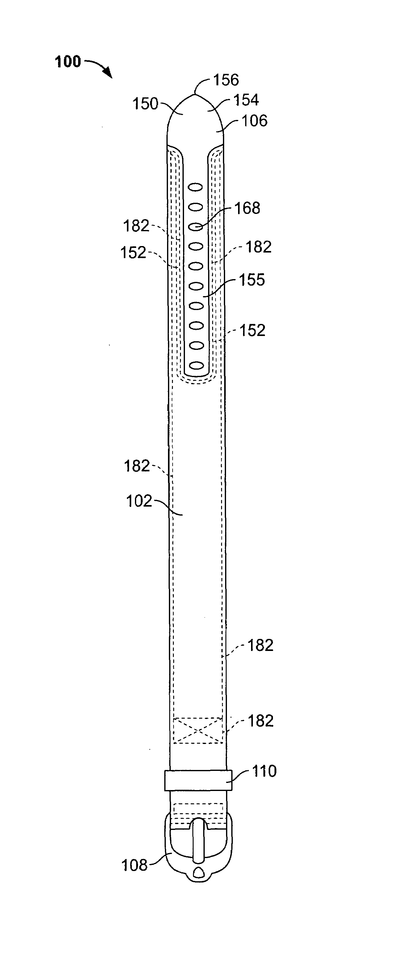
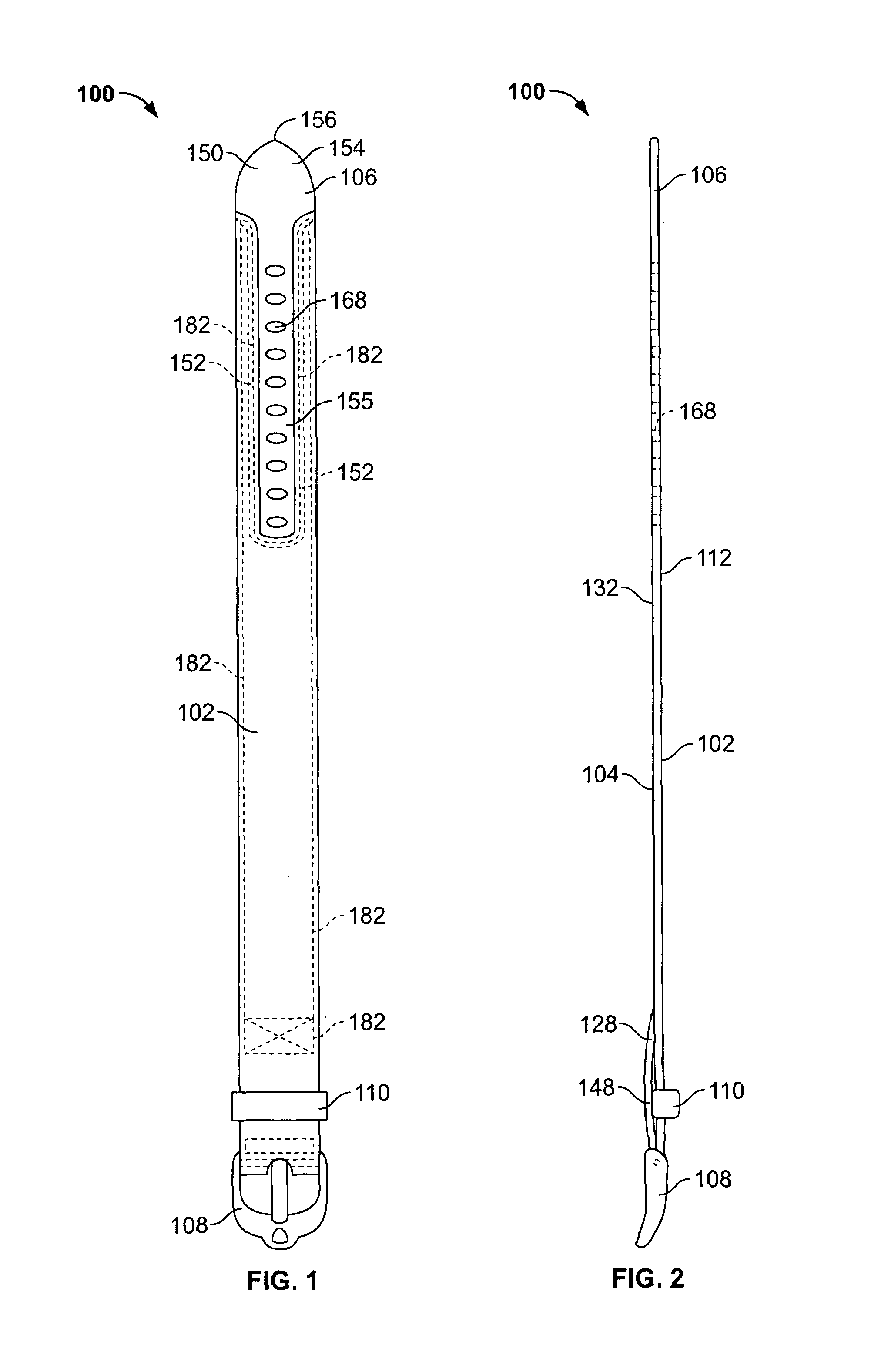
[0034]Attention is now directed to the watch band construction 100 of the invention as illustrated in FIGS. 1-9. A final construction of a watch band 100 of the present invention is illustrated in FIGS. 1 and 2. The watch band construction 100 includes a top layer 102, a bottom layer 104, an insert 106, a buckle 108, and a keeper 110.

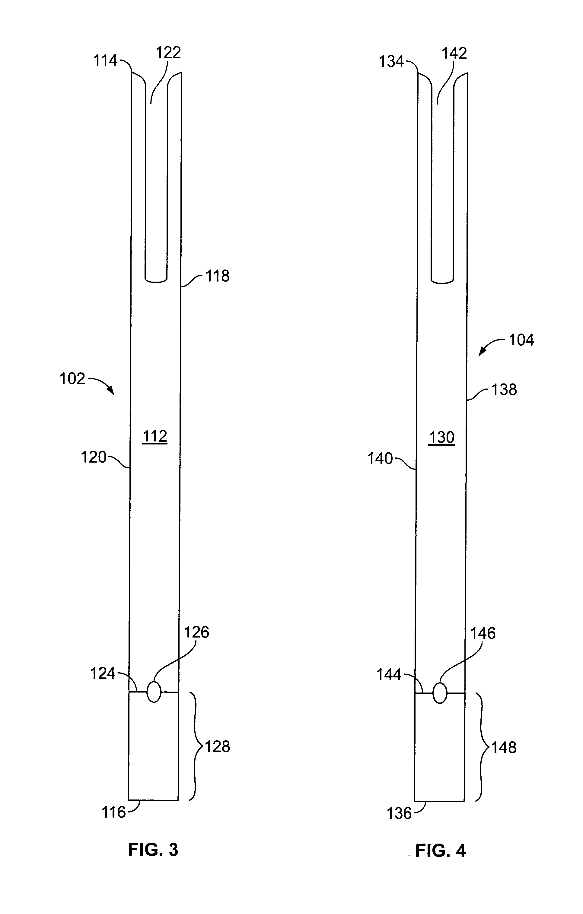
[0035]The top layer 102 of the watch band 100 is best illustrated in FIG. 3. The top layer 102, in the final construction of the watch band 100, acts as the exterior side of the watch band 100, i.e., the side of the watch band 100 which does not typically contact the user's skin. The top layer 102 is preferably formed of nylon.

[0036]The top layer 102 is preferably rectangular in construction such that it has a top surface 112, a bottom surface (not shown), a first or tip end 114, a second end 116 which is opposite the tip end 114, a first side edge 118 which extends from one end of the tip end 114 to one end of the second end 116, and a second side edge...

second embodiment

[0055]Attention is now directed to the watch band construction 200 of the invention as illustrated in FIGS. 10-19. A final construction of a watch band 200 of the present invention is illustrated in FIGS. 10 and 11. The watch band construction 200 includes a top layer 202, a bottom layer 204, an insert 206, a buckle 208, and a keeper 210.

[0056]The top layer 202 of the watch band 200 is best illustrated in FIG. 12. The top layer 202, in the final construction of the watch band 200, acts as the exterior side of the watch band 200, i.e., the side of the watch band 200 which does not typically contact the user's skin. The top layer 202 is preferably formed of nylon.

[0057]The top layer 202 is preferably rectangular in construction such that it has a top surface 212, a bottom surface (not shown), a first or tip end 214, a second end 216 which is opposite the tip end 214, a first side edge 218 which extends from one end of the tip end 214 to one end of the second end 216, and a second side...


PUM


Abstract

The present invention provides a watch band construction which includes a top layer, a bottom layer and an insert. The top and bottom layers each have an aperture provided proximate to the tip ends thereof. The insert is positioned between the top and bottom layers within the apertures and is stitched to the top and bottom layers to secure the insert between the top and bottom layers. The insert provides the tip for the watch band, as well as the holes through which the buckle prong extends. The tip may be formed with raised portions and the holes may be formed with angled walls at the bottom of the insert. The insert is formed with a curve bias along both a length and width thereof. The insert is formed of a sturdy material, such as resin, such that it is durable and long lasting in the areas of high wear.

Description

CROSS-REFERENCE[0001]This patent application claims the benefit of domestic priority of U.S. Provisional Application Ser. No. 60 / 475,764, filed Jun. 4, 2003, and entitled “Watch Band Construction”.BACKGROUND OF THE INVENTION[0002]The present invention relates to a novel construction for a watch band.[0003]Woven materials, such as cloth, fabric, nylon, polyester, cotton, and polypropylene, tend to fray, become loosened, unraveled, or un-woven on all “raw edges” or edges that are cut during the fabrication process in making a finished good. One such finished good on which this typically occurs is a watch band.[0004]The “raw edges” on a watch band are typically the tip end and the holes that are cut for a buckle prong, which are high wear areas. As a user puts on and takes off the watch, the holes and tip become increasingly worn out as the weaker woven material contacts the metal buckle and the buckle prong. This repeated use reduces the durability and life of the watch band. In some ...

Claims


Application Information

Patent Timeline
Patent Type & Authority Patents(United States)
IPC IPC(8): A44B1/04A44B11/25A44C5/00
CPCA44C5/0053
Inventor BERTUCCI, MICHAEL H.
Owner MH BERTUCCI
Why Eureka
Try Eureka