
System and method for detecting position offset of chip

A technology for detecting chips and chips, which is applied in the direction of measuring devices, optical devices, instruments, etc., can solve the problems of easy leakage detection of chips, achieve the effects of improving detection accuracy, improving automatic detection efficiency, and avoiding leakage detection.

Inactive Publication Date: 2019-07-16
GRAND TECH SHENZHEN
View PDF17 Cites 0 Cited by
  • Summary
  • Abstract
  • Description
  • Claims
  • Application Information

AI Technical Summary

Problems solved by technology

However, there are obvious loopholes in this method, especially when detecting chips with small size or serious position deviation, it is often easy to miss detection.

Method used


Image

  • System and method for detecting position offset of chip
  • System and method for detecting position offset of chip
  • System and method for detecting position offset of chip

Examples


Embodiment Construction

[0023] The specific implementation manners of the present invention will be further described in detail below in conjunction with the accompanying drawings and embodiments. The following examples are used to illustrate the present invention, but are not intended to limit the scope of the present invention.

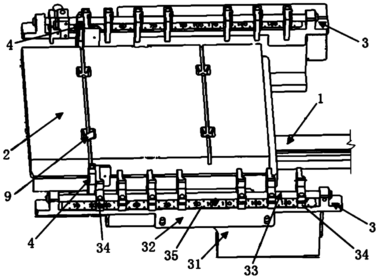
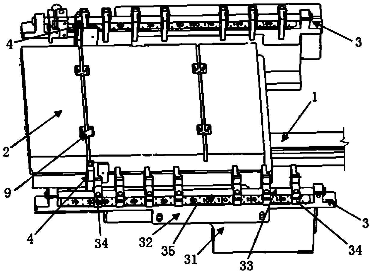
[0024] Please refer to the attached figure 1 , a system for detecting chip position offset provided by the present invention, which includes:

[0025] A chip conveying device, the chip conveying device comprising a guide rail 1, a jig 2 mounted on the guide rail 1 and capable of moving along the guide rail 1;

[0026] A chip detection device, the chip detection device includes a sensor mounting structure 3 arranged along both sides of the guide rail 1 and a light curtain facing sensor 4 connected to the sensor mounting structure 3;

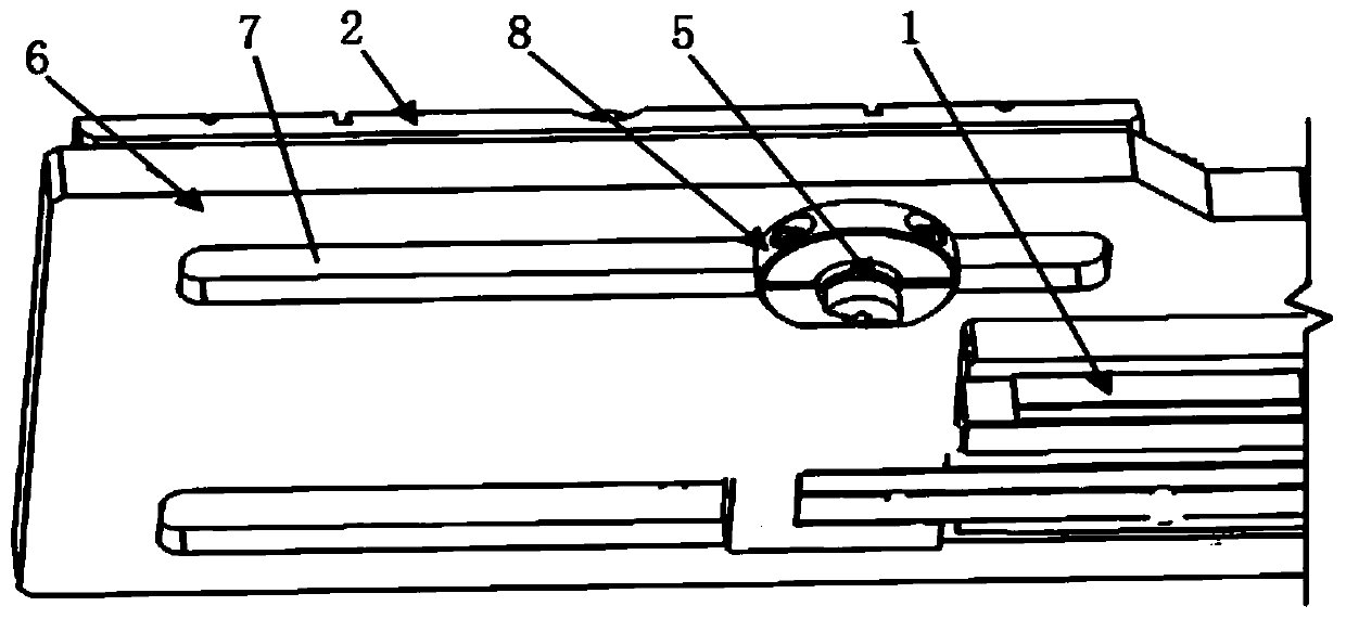
[0027] A position correcting device, the position correcting device includes a vibrating mechanism 5 relatively fixedly connected with the ...


PUM


Abstract

The invention discloses a system and method for detecting position offset of a chip. The system comprises the following parts of a chip conveying device comprising a guide rail and a jig mounted on the guide rail and movable along the guide rail; a chip detecting device comprising a sensor mounting structure disposed along both sides of the rail and a light curtain shooting sensor coupled to the sensor mounting structure; and a position correcting device comprising a vibrating mechanism with a fixed connection to the jig. The system and method provided by the invention greatly improve the detection precision and can avoid the leakage detection phenomenon of the existing point or line sensor by setting the light curtain shooting sensor, and can vibrate the chip with position offset to flatin time, avoid the chip with position offset from flowing into the next process to damage the chip and improve the automatic detection efficiency by setting the vibration mechanism connected to the jig.

Description

technical field [0001] The invention relates to the technical field of chip detection, in particular to a system and method for detecting chip position deviation. Background technique [0002] In the production process of the chip, after the chip is placed in the groove of the jig, it is necessary to test chips of different sizes and thicknesses according to the testing requirements. At present, point or line-to-shoot sensors are mainly used to detect the presence or absence of chips and the phenomenon of positional deviation. However, there are obvious loopholes in this method, especially when detecting chips with small size or serious position deviation, it is easy to miss detection. Therefore, it is necessary to adopt a new detection method to avoid the disadvantages of point and line-to-shoot sensors. Contents of the invention [0003] The object of the present invention is to provide a system and method for detecting chip position deviation, avoid the missing detect...

Claims


Application Information

Patent Timeline
Patent Type & Authority Applications(China)
IPC IPC(8): G01B11/00
CPCG01B11/00
Inventor 林宜龙刘飞张礼军涂前超张福威刘秋强徐梦华
Owner GRAND TECH SHENZHEN
Learn More