Running machine with automatic dedusting function

An automatic dust removal and treadmill technology, applied in the field of treadmills, can solve problems such as damage to treadmills and shortened service life of treadmills, and achieve the effects of prolonging service life, simple operation and reducing frictional resistance.

Inactive Publication Date: 2019-07-19
福建大威科技有限公司
View PDF5 Cites 7 Cited by
  • Summary
  • Abstract
  • Description
  • Claims
  • Application Information

AI Technical Summary

Problems solved by technology

[0003] There is no corresponding dust collection equipment on the existing treadmill, because the user’s soles are usually glued with sundries or mud, so there is no corresponding dust collection equipment for the protection of the treadmill, and these sundries or mud will inevitably damage the treadmill. To the treadmill, the service life of the treadmill is greatly shortened, so we propose a treadmill with automatic dust removal to solve the above-mentioned problems

Method used


Image

  • Running machine with automatic dedusting function
  • Running machine with automatic dedusting function
  • Running machine with automatic dedusting function

Examples


Embodiment 1

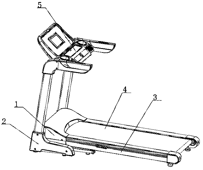
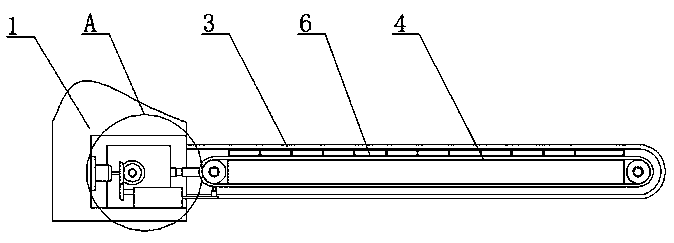
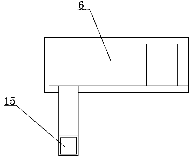
[0031]refer to Figure 1-10 , a treadmill with automatic dust removal is proposed in this embodiment, including a mounting base 1, a mounting frame 2 is fixedly installed on the mounting base 1, a control panel 5 is fixedly mounted on the top of the mounting frame 2, and one side of the mounting base 1 is symmetrical Two installation covers 3 are fixedly installed, and the same running belt 4 is arranged in the two installation covers 3, and a dust collection cover 6 is fixedly installed in the installation cover 3, and the dust collection cover 6 is positioned at the top of the running belt 4, and the dust suction The inner wall of the bottom of the cover 6 is sealed and fixed with an L-shaped pipe 15, and one side of the mounting seat 1 is provided with a connecting groove 7, and two fixing seats 8 are symmetrically fixed on the inner wall of the bottom of the connecting groove 7. A collection chamber 16 is provided, and the two collection chambers 16 are rotatably connected...

Embodiment 2

[0039] refer to Figure 1-10 The difference between the automatic dust-removing treadmill proposed in this embodiment and the first embodiment is that:

[0040] In this embodiment, a ball screw nut 36 is rotatably connected in the limit groove 35 , and the ball screw 38 penetrates the ball screw nut 36 and is threadedly connected with the ball screw nut 36 , so as to apply force to the torsion spring 37 conveniently.

[0041] In this embodiment, a limit ring is fixedly installed on the inner wall of the limit groove 35, and the limit ring is located on one side of the ball screw nut 36, and the ball screw 38 runs through the limit ring and is slidably connected with the inner wall of the limit ring. A torsion spring 37 is sleeved on the ball screw 38, and the torsion spring 37 is located between the spacer ring and the ball screw nut 36, and the two ends of the torsion spring 37 are fixedly connected with the spacer ring and the ball screw nut 36 respectively. The torsion spr...


PUM


Abstract

The invention belongs to the field of running machines, and particularly relates to a running machine with an automatic dedusting function, aiming to solve the problem of greatly shortened service life of existing running machines due to the fact that impurities, namely dust, are easily adhered to the running machines free of corresponding dust removers to easily damage the running machines. The running machine comprises a mounting base. A mounting frame is fixedly mounted on the mounting base, a control panel is fixedly mounted at the top of the mounting frame, and two mounting covers are symmetrically and fixedly mounted on one side of the mounting base. The running machine has the advantages that the running machine is simple to operate; through startup of a driving motor, a worm gear blade can rotate to remove the dust; a cleaning brush can reciprocate horizontally to clean a running belt, so that the friction resistance of the running belt during transmission is reduced; the bodyof the running machine is kept clean and neat, energy saving is achieved, the service life of the whole machine is effectively prolonged, and the dust at dead angles of the machine is conveniently cleaned.

Description

technical field [0001] The invention relates to the technical field of treadmills, in particular to an automatic dust-removing treadmill. Background technique [0002] Treadmill is a common fitness equipment for families and gyms, and it is the simplest type of home fitness equipment today, and it is the best choice for home fitness equipment. In 1965, Nordic Finland Dontley produced the world's first household treadmill, which was changed by the designer based on the principle of the speed belt. [0003] There is no corresponding dust collection equipment on the existing treadmill, because the user’s soles are usually glued with sundries or mud, so there is no corresponding dust collection equipment for the protection of the treadmill, and these sundries or mud will inevitably damage the treadmill. To the treadmill, the service life of the treadmill is greatly shortened, so we propose a treadmill with automatic dust removal to solve the above-mentioned problems. Contents...

Claims


Application Information

Patent Timeline
Patent Type & Authority Applications(China)
IPC IPC(8): A63B22/02B08B1/00B08B5/04
CPCA63B22/02B08B1/002B08B1/005B08B5/04
Inventor 刘步永
Owner 福建大威科技有限公司
Why Eureka
Try Eureka