
Step-by-step secondary core-pulling demolding device with transverse sliding block for injection mold

A transverse sliding block and secondary core pulling technology, applied in the field of demolding devices, can solve the problems of low efficiency, low production efficiency, high work intensity, etc., and achieve the effects of reducing cost, improving efficiency and reducing work intensity

Inactive Publication Date: 2019-07-19
宁波和鑫光电科技有限公司
View PDF0 Cites 0 Cited by
  • Summary
  • Abstract
  • Description
  • Claims
  • Application Information

AI Technical Summary

Problems solved by technology

[0003] If there is a deep groove structure on the outside of the product, the flange corresponding to the horizontal slider will also be deep. After the product is formed, it will have a large covering force on the profile of the horizontal slider. If the horizontal slider forcibly pulls the core and removes the mold, the product will be strained and deformed; thus, the above-mentioned structure of the product is called a large covering force structure; for the large covering force structure, the prior art adopts the insert method for molding And core-pulling demoulding, that is, making a corresponding core block-shaped insert in advance according to the shape of the large covering force structure; when the product is formed, the insert is manually placed on the profile of the horizontal slider, and the product is demoulded after forming At the same time, the insert is demoulded together with the product, and then the insert is removed from the product manually with the help of tools; in this way, the injection molding production has high work intensity, low production efficiency, and high overall cost. Therefore, the existing technology exists The problems and deficiencies of high work intensity, low efficiency and high cost

Method used


Image

  • Step-by-step secondary core-pulling demolding device with transverse sliding block for injection mold
  • Step-by-step secondary core-pulling demolding device with transverse sliding block for injection mold
  • Step-by-step secondary core-pulling demolding device with transverse sliding block for injection mold

Examples


Embodiment Construction

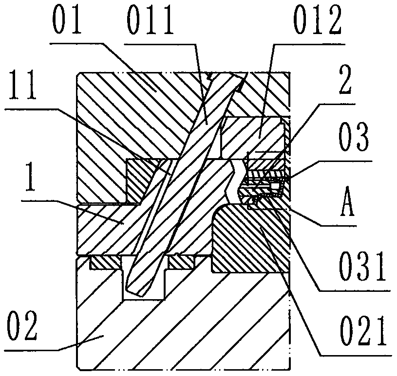
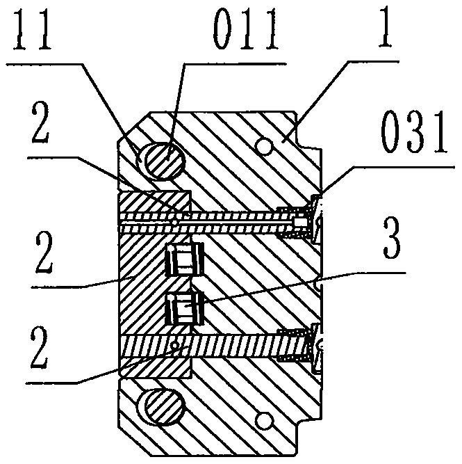
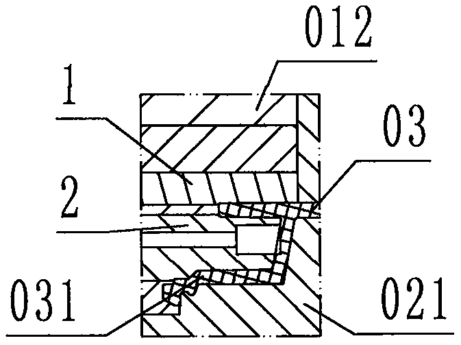
[0028] refer to Figure 1 to Figure 9 , a step-by-step secondary core-pulling demoulding device for a lateral slider of an injection mold, comprising a lateral slider 1, a first core-pulling block 2 and a spring 3, wherein: the first core-pulling block 2 is closed on the left side 1. The right side is open, rectangular ring frame-shaped block steel member, the left side of the left frame wall of the core block 2 is an inclined plane inclined from top to bottom; The surface corresponding to the large covering force structure 031 of the product 03 is respectively called the drawing surface;

[0029] The transverse slider 1 is a wedge-shaped steel member, the left side of the transverse slider 1 is a slope inclined from top to bottom to the left, and the right side of the transverse slider 1 is provided with a corresponding The shape surface is called the block surface, and the top of the horizontal slider 1 is provided with a groove corresponding to the shape of the first core-...


PUM


Abstract

The invention discloses a step-by-step secondary core-pulling demolding device with a transverse sliding block for an injection mold. The step-by-step secondary core-pulling demolding device comprisesthe transverse sliding block (1), a first core-pulling block (2) and a spring (3). According to the technical scheme adopted by the step-by-step secondary core-pulling demolding device, the first core-pulling block is provided with a pulling mold face; the transverse sliding block is provided with a block mold face, a first pulling groove and a delay oblique guide hole; the first core-pulling block is slidably located in the first pulling groove, and the spring is located between the first core-pulling block and the left side wall of the first pulling groove; and the transverse sliding blockis slidably buckled on the upper face of a movable mold carrying plate, and in a mold closing state, a mold cavity for a molded product and a large-covering-force structure is defined jointly by the block mold face, the pulling mold face, a fixed mold cavity and a movable mold core; during working, due to the effect of the spring, the first core-pulling block firstly moves leftwards to drive the pulling mold face to pull the core out of the large-covering-force structure, and then an oblique guide column drives the transverse sliding block and the first core-pulling block to together move leftwards to enable the block mold face to be separated from the product. Thus, in injection molding production of the injection mold of the large-covering-force structure product, the purposes of reducing work intensity, improving efficiency and lowering costs are achieved.

Description

technical field [0001] The invention relates to a demoulding device for an injection mold, in particular to a step-by-step secondary drawing of a lateral slide block of an injection mold used to pull a core-pulling block out of a large coating force structure of a product in an injection mold. Core stripping device. Background technique [0002] Explanation: In the injection mold, the opening and closing direction of the mold is called the longitudinal direction, the direction perpendicular to the longitudinal direction is called the transverse direction, and the direction between the longitudinal direction and the transverse direction is called the oblique direction. The horizontal slider is a component used for molding the outer surface of the product by the injection mold and performing horizontal core-pulling and demoulding after molding; [0003] If there is a deep groove structure on the outside of the product, the flange corresponding to the horizontal slider will al...

Claims


Application Information

Patent Timeline
Patent Type & Authority Applications(China)
IPC IPC(8): B29C45/44B29C45/26
CPCB29C45/2602B29C45/44
Inventor 李和鑫汪锋
Owner 宁波和鑫光电科技有限公司
Learn More