Wall Mounted Aluminum Electrolytic Cathode

A technology for aluminum electrolysis and aluminum electrolysis cell, which is applied in the field of wall-type aluminum electrolysis cathode structure, can solve problems such as insufficient energy saving, and achieve the effects of avoiding scouring, facilitating maintenance and replacement, and solving poor stability.

Active Publication Date: 2020-10-16
CENT SOUTH UNIV
View PDF5 Cites 0 Cited by
  • Summary
  • Abstract
  • Description
  • Claims
  • Application Information

AI Technical Summary

Problems solved by technology

[0006] The technical problem to be solved by the present invention is to provide a wall-type aluminum electrolysis cathode with a new arrangement for the problem of insufficient energy saving in the existing aluminum electrolysis cell cathode structure

Method used


Image

  • Wall Mounted Aluminum Electrolytic Cathode
  • Wall Mounted Aluminum Electrolytic Cathode
  • Wall Mounted Aluminum Electrolytic Cathode

Examples


Embodiment 1

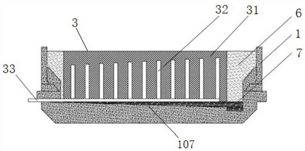
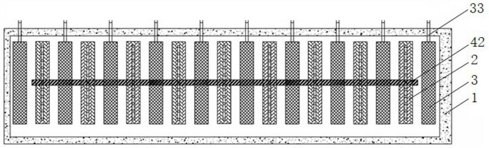
[0028] see Figure 1-4 , the aluminum electrolytic cell in the diagram is a specific implementation of the wall-type aluminum electrolytic cathode of the present invention, specifically as figure 1 As shown, the cathode 3 is a plate-shaped structure, which is fixedly arranged inside the cell body 1 of the aluminum electrolytic cell along the vertical direction, and the bottom of the cathode 3 is fixedly placed on the bottom of the cell body 1, and in the cell body of the aluminum electrolytic cell A structure similar to a partition is formed inside, and the anode 2, which is also a plate-shaped structure, separates the interior of the aluminum electrolytic cell into at least two electrolytic chambers, such as figure 2 As shown, all the electrolysis chambers are distributed along the horizontal direction, and the anode 2 and the cathode 3 are respectively located on both sides of the electrolysis chamber, and the electrolyte between the anode 2 and the cathode 3 is vertically ...

Embodiment 2

[0037] see Figure 5 , the aluminum electrolytic cell shown in the illustration is another specific implementation of the wall-type aluminum electrolytic cathode of the present invention. The difference between the cathode 3 in this embodiment and the first embodiment is that the horizontal set inside the cathode carbon block 31 The cross section of the current collecting steel rod 33 increases with the distance away from the cathode busbar, that is, the cross section of the horizontal current collecting steel rod 33 is of different sizes gradually, the cross section is still square, and the width of the cross section is uniform, 150mm, away from the horizontal The section height inside the anode carbon block at the extension end of the collector steel rod 33 is 10-50mm higher than the section height at the extension position.


PUM


Abstract

The invention discloses a wall type aluminum electrolysis cathode. The cathode is of a plate-shaped structure and is fixedly arranged at the bottom of a tank chamber of an aluminum electrolysis tank in the vertical direction, the cathode and an anode which is also of a plate-shaped structure partition the interior of the aluminum electrolysis tank into at least two electrolysis chambers distributed in the horizontal direction, and the cathode comprises a cathode carbon block and a cathode conducting steel rod. According to the wall type aluminum electrolysis cathode, the cathode can partitiona fiercely fluctuating melt area in the aluminum electrolysis tank into multiple oxidizing chambers capable of continuously running together with the aluminum electrolysis anode, influences of disturbance currents on the electrolysis tank magnetofluid stability are thoroughly eliminated, and the wall type aluminum electrolysis cathode is a novel cathode structure capable of ensuring deep energy conservation and environmental protection of multi-chamber continuous aluminum electrolysis.

Description

technical field [0001] The invention belongs to the aluminum electrolysis cell technology, in particular to a wall-type aluminum electrolysis cathode structure. Background technique [0002] The Hall-Héroult aluminum electrolysis process has always been the only method for industrial aluminum smelting, and its core reaction is carried out in the aluminum electrolytic cell. The cathode of the current aluminum electrolytic cell is a part of the lining, which is placed horizontally on the bottom of the aluminum electrolytic cell as a plane with aluminum liquid on it as the real cathode. Although the capacity of this type of electrolytic cell has reached 600kA, this type of electrolytic cell Slots have a number of drawbacks: [0003] 1. The electrolytic reaction interface of the aluminum electrolytic cell is horizontal, so the larger the electrolytic cell, the larger the area occupied by the electrolytic cell, resulting in increased construction and operating costs of the elect...

Claims


Application Information

Patent Timeline
Patent Type & Authority Patents(China)
IPC IPC(8): C25C3/08
CPCC25C3/08
Inventor 张红亮王佳成李劼李天爽张凯于心岩国辉李家琦孙珂娜
Owner CENT SOUTH UNIV
Why Eureka
Try Eureka